Part of the Collection section. Collector bodies and outlet tubing that route juice to third-party tanks/pumps, and provide a reverse-flow CIP path.
Introduction
The juice collectors capture juice exiting the filter tube slots and route it out of the machine through sanitary tubing and quick-connect interfaces. The collectors are also intended to support a reverse-flow CIP mode that flushes cleaning fluid back through the filter tubes and out the plug cutters.
Colour key & components
Key components and intent (colours may vary across CAD figures).
Colour(s)
Component
—
Collector body — 304 stainless tube assembly (concept: standard tube sizes; main body ~57 mm OD chosen for availability, not a hard requirement); food-zone interior surface roughness target Ra ~0.8 μm.
—
Outlet tube — concept sized for common quick-connects; current intent is ~38 mm OD outlet to rubber hose via ribbed adapter.
—
Quick-connect interface — standard sanitary ferrule/flange that mates to the downstream ribbed rubber connection (choose a common China-available quick-connector spec where possible) for fast disconnect.
—
T-valve / switching — concept to switch between "juice to tank" vs "CIP fluid into collector".
Figures
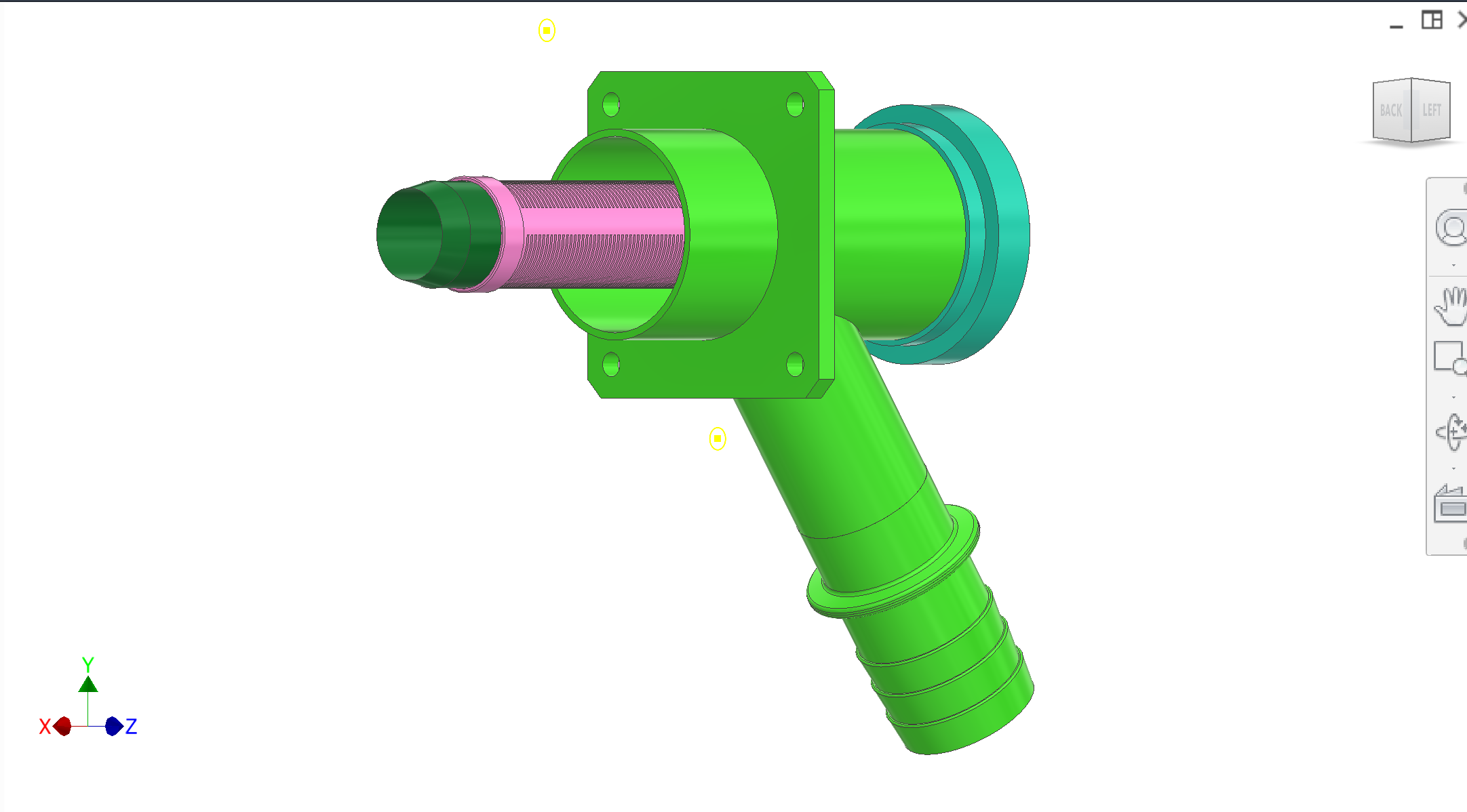
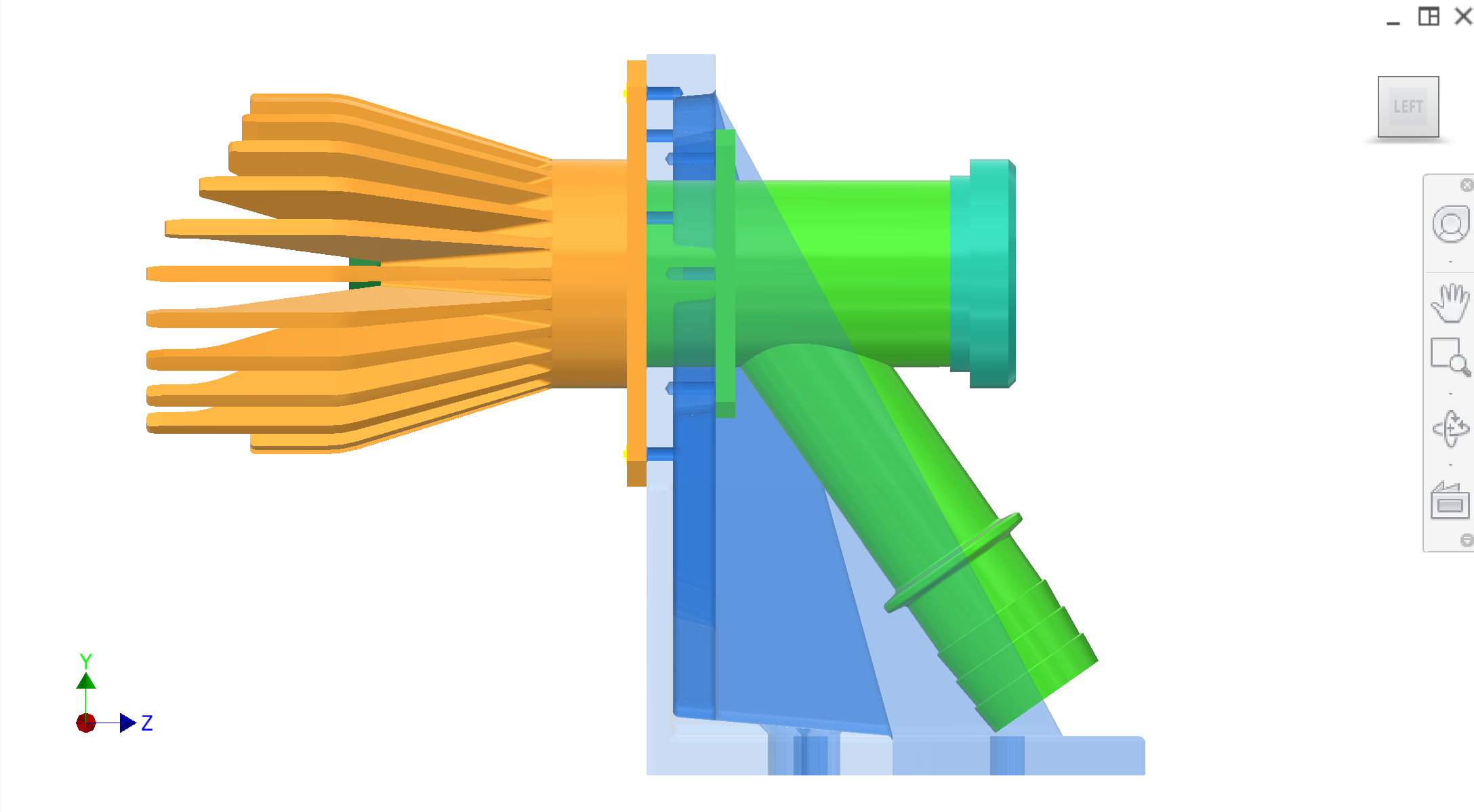
System context remains in the Collection main gallery. Below: collector + filter relationship and a side view of the juice-collection subassembly. Figure 1; Figure 2.
Figure 1. Collector and filter — assembly relationship (photo).Figure 2. Side view — juice collection subassembly profile.
Recommended figures (contractor clarity)
Add figure: tube size callouts (main body OD, outlet OD/ID) and welded fitting types.
Add figure: downstream quick-connect + ribbed hose adapter example part and how it mates to rubber hose.
Forward flow — Juice exits through filter tube slots into the collector body and then out through the outlet tube to third-party tanks/pumps.
Standard tube sizes — Current concept uses 304 stainless tube sizes selected for availability (main body ~57 mm OD; outlet sized for common quick-connect and hose hardware).
Surface finish requirement — Interior food-zone surfaces must be fabricated/finished to remain cleanable (target Ra ~0.8 μm unless contractor proposes an alternate hygiene-validated surface finish).
CIP concept (reverse flow)
Switching — A T-valve is used to select between "juice out" vs "CIP fluid in".
Flow direction — CIP fluid enters via the outlet tube and floods the collector chamber, then flows through the filter tube and exits out the plug cutter centreline to flush the slots and internal passages.
Known issues & risks
Cleaning dead zones — Contractor to identify any stagnant regions in collector geometry where pulp could accumulate and propose drain/flush improvements.
Connection standards — Need to pick a consistent CN-available quick-connect standard (Tri-Clamp or equivalent) and seal materials compatible with CIP chemicals.
Questions for contractor
Recommend CN-available sanitary/quick-connect standard(s) and specific tube sizes (OD/ID) to meet flow and cleanability requirements.
Validate the reverse-flow CIP concept and propose required valves/check valves, pressure limits, and maintenance/cleaning protocol.
Propose a robust, serviceable ribbed hose adapter and quick-connection strategy for the outlet tube (include sourcing options in China).
Interfaces
Input: Juice from filter tube slots.
Output: Outlet tube to third-party plumbing; CIP inlet path in reverse-flow mode.
Mount: Collectors mount on the collection mount plate and interface with static peeler/collector geometry.
Interfaces and tolerances
Known interfaces and tolerances. Links go to related subsystems.
Part
Interface / tolerance
Related
Collector body
Standard 304 stainless tube assembly; interior food-zone target Ra ~0.8 μm (cleanability requirement). Main body ~57 mm OD concept (availability-driven; may change)