The feeder body is the structural shell and lid assembly within the fruit intake system. It supports the per-station feeding subassemblies and entry tubes, provides splash containment for the extraction zone, and opens on a hinge for maintenance access and CIP washdown.
Introduction
The feeder body is the structural "shell" that supports the per-station feeding subassemblies and entry tubes. It is designed to open on a hinge for access and cleaning. It also provides splash control so juice and cleaning spray stay inside the extraction zone and drain toward disposal.
Colour key & components
Key elements and intent (colours may vary across CAD figures).
Colour(s)
Component
—
Feeder body / shell — sheet-metal enclosure that supports feeding subassemblies and creates splash containment.
—
Top lid — concept: ~2 mm sheet steel lid panel; mounts to hinge and bracing; provides access for service/CIP.
—
Brace / bracing — structural reinforcement to prevent lid buckling and distribute hinge loads; design still TBD (folded vs welded ribs/stiffeners).
—
Feeding-subassembly cutouts — diagonal cutouts/ports where feeding subassembly mount plates sit; intended to be modular (riveted) for iteration.
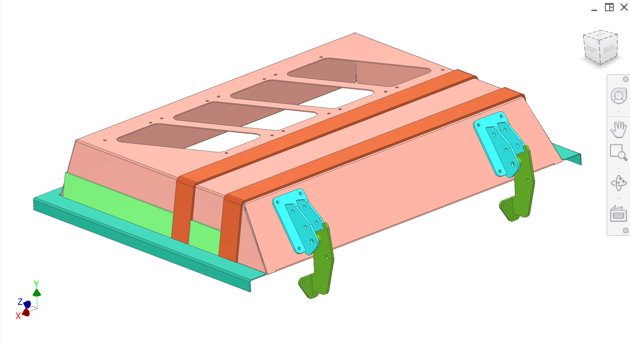
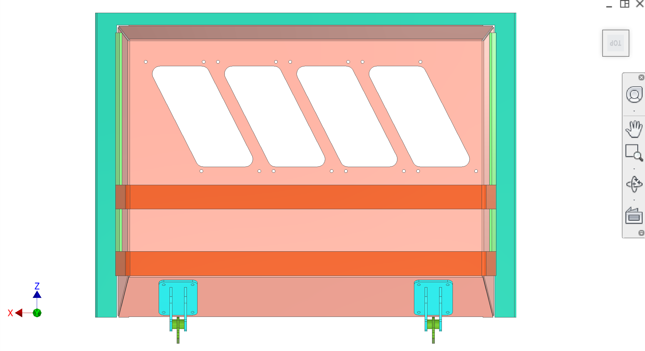
Figure 1. Isometric — feeder body / shell with hinge in context.Figure 2. Top — feeder body with hinge and feeding-subassembly openings.
Recommended figures (contractor clarity)
Add figure: lid / shelf lip geometry showing how the lid overhangs into the extraction zone to keep spray inside (splash containment intent).
Add figure: hinge load path — bracing / reinforcement concept so hinge reactions do not load thin ~2 mm sheet alone (Figures 1–2 show hinge placement; detail still useful).
Add figure: feeding-subassembly mount cutouts and rivet pattern on the shell (modular swap) with callouts.
Discussion
Rough design & intent
Purpose — Provide a rigid, cleanable housing for the fruit intake mechanism while allowing rapid access for maintenance and CIP/washdown.
Modularity — Feeding subassemblies (mount plate + tubes + sync spring) are designed to be built as a module, then riveted onto the feeder body. Tubes can be swapped by drilling out rivets as the design evolves.
Known issues & risks
Splash containment — Lid and "shelf lip" geometry must keep juice/spray inside the extraction zone. The lid should overhang inward so upward spray drains back into the extraction/disposal region rather than escaping to outer walls.
Bracing/hinge loads — The lid is thin sheet (concept ~2 mm). Hinge mounts must land on reinforced bracing, not directly on thin sheet, to avoid tear-out and buckling.
Edge safety — All cut edges must be deburred/hemmed so operators are not cut during seasonal teardown/cleaning.
DFM & manufacturing (China)
Sheet metal process — Contractor to propose fold vs weld strategy for the shell and bracing. Prefer folded hems and continuous seams where possible in splash zones.
Rivets vs welded studs — Riveted modular mounts are acceptable for iteration; contractor may propose better hygienic fastening (studs outside splash zone, weld studs, etc.) for production-ready design.
Questions for contractor
Propose the feeder shell fabrication method (folded sheet vs welded) that achieves stiffness and good hygiene (no pockets, good drainage) with China-available processes.
Propose a hinge + bracing design that distributes loads safely into the shell without local buckling/tear-out.
Review the lid lip/overhang geometry to ensure spray containment and drainage into the extraction zone.
Interfaces
Input: Fruit enters via entry tubes from upstream sorter/lines.