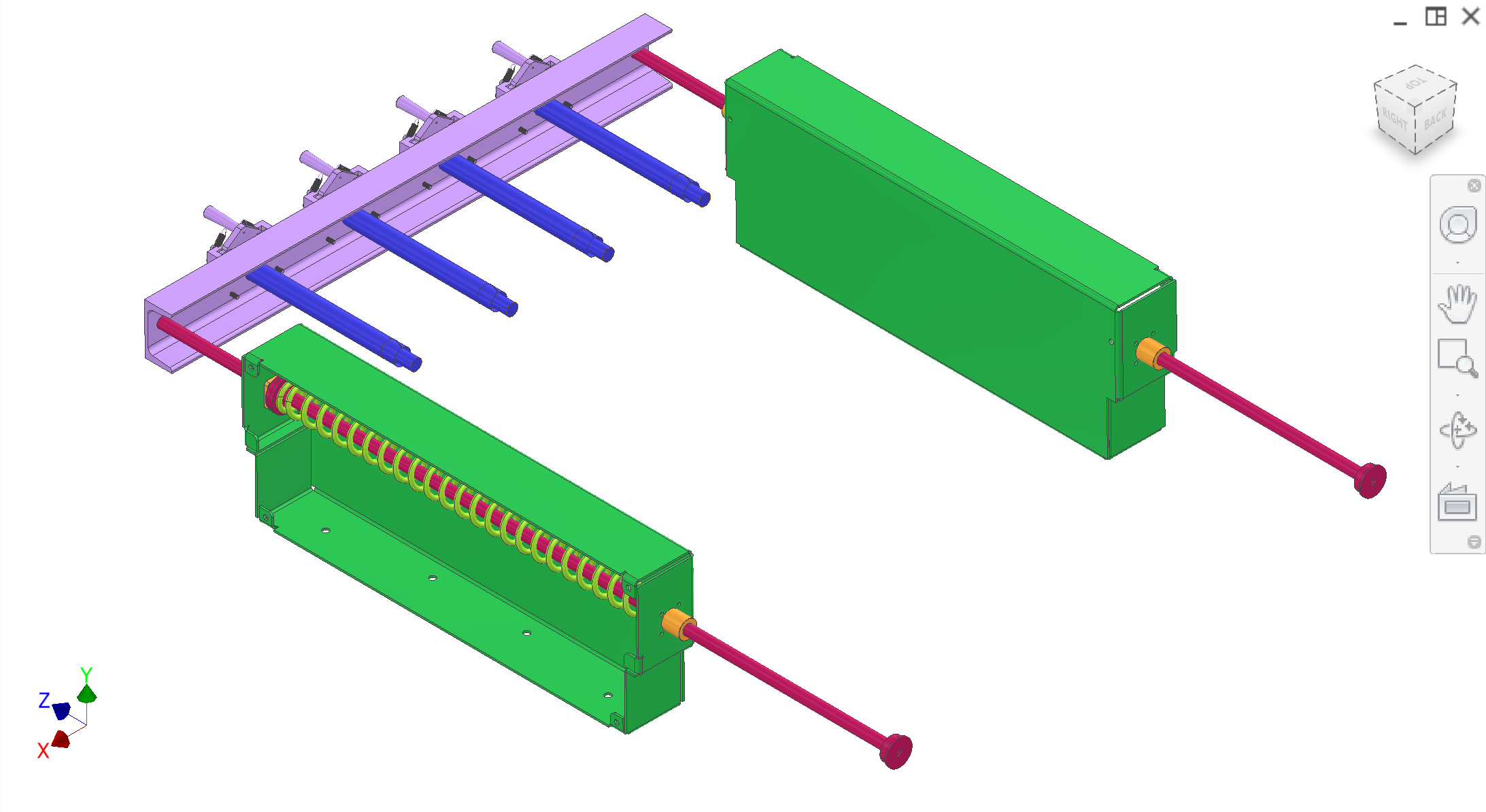
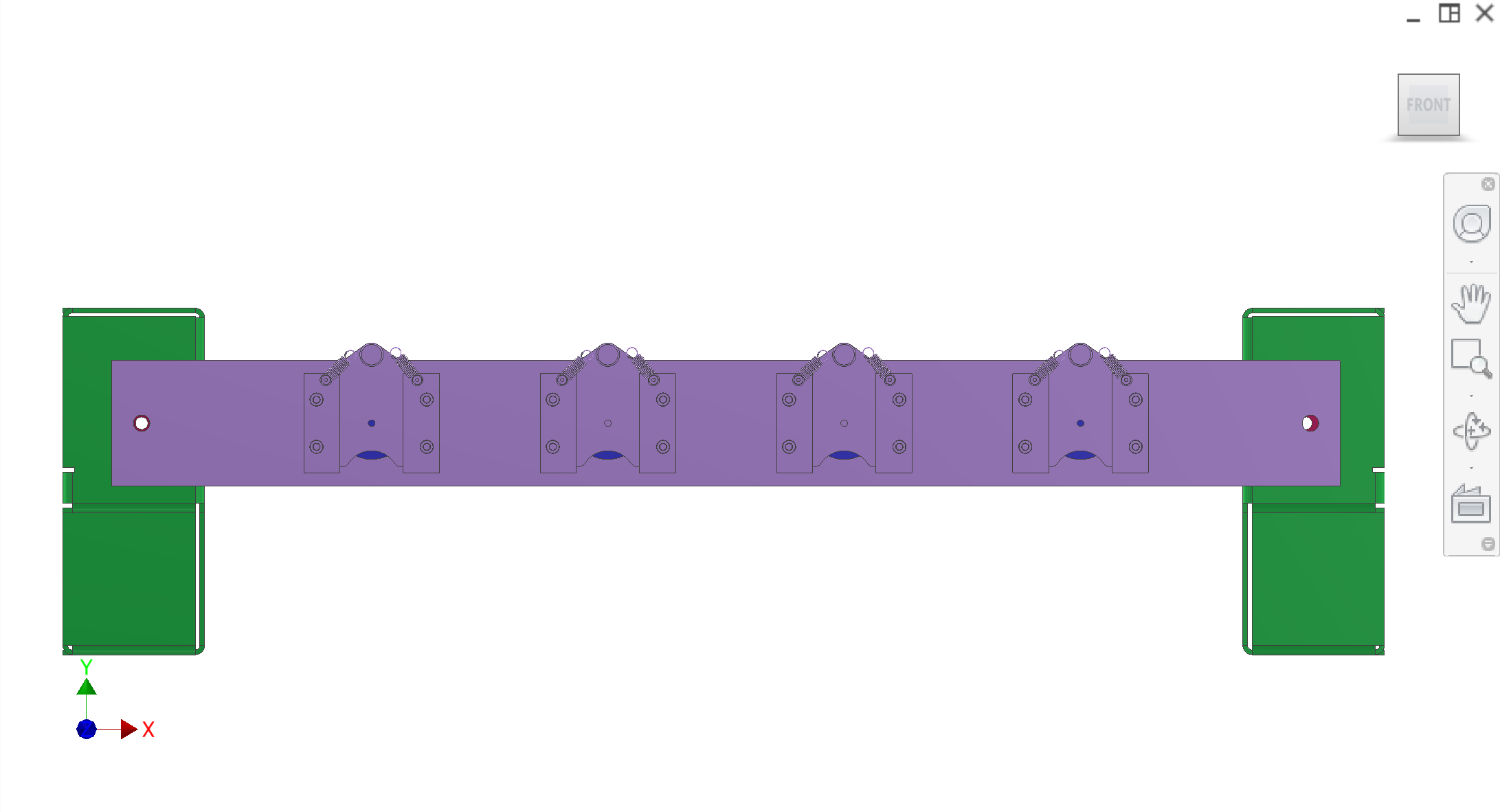
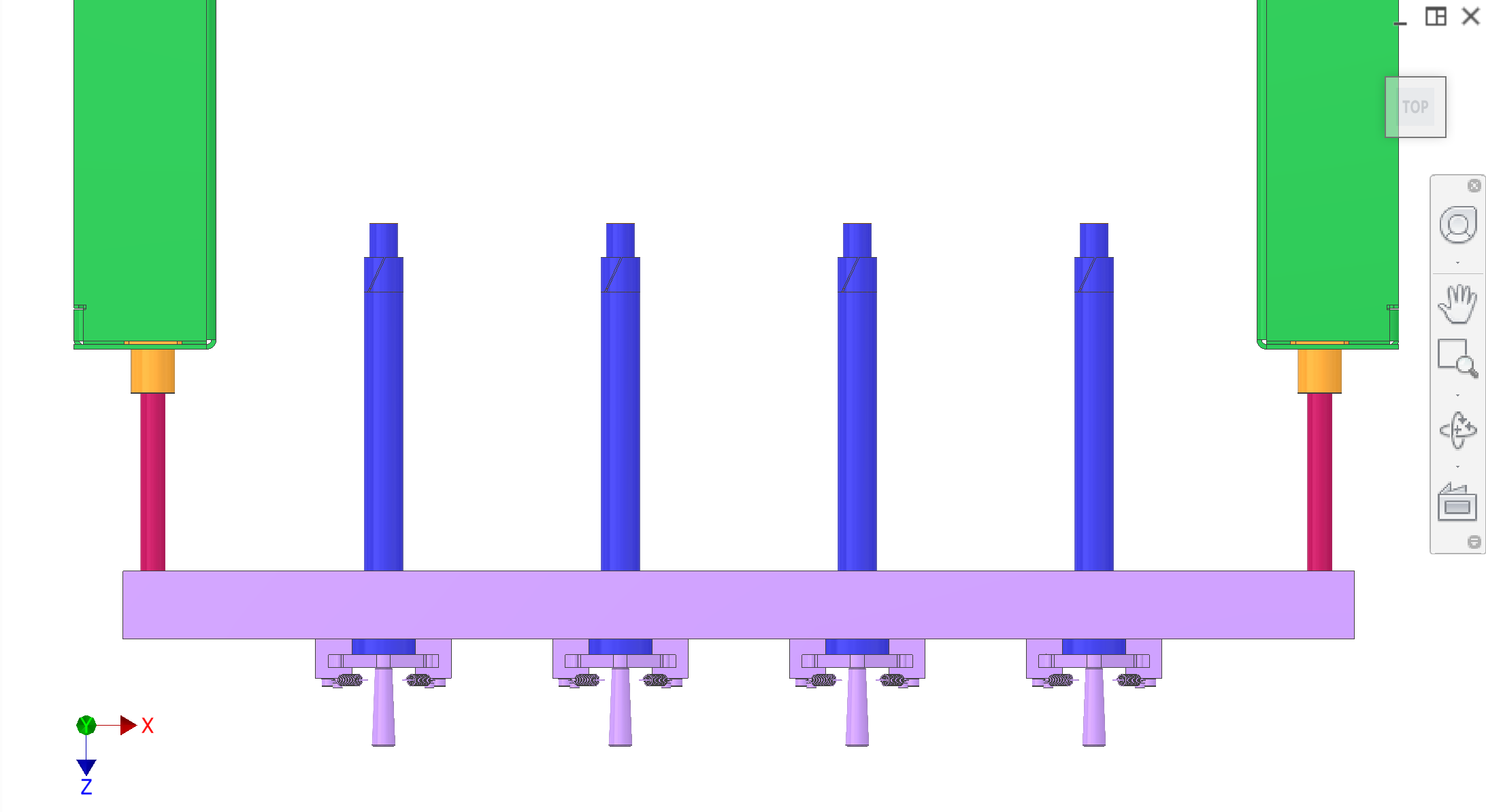
The core ejection system (subsystem 7) removes the pressed orange core from the plug cutter and drops it into the disposal system's core chute. It uses compression-spring-driven plungers mounted on a drive bracket, actuated through linear-bearing-guided drive rods housed in the side panels. The transmission yoke pulls the drive rods back against the springs during the return stroke; on release, the springs push the plungers forward through the filter tube to eject the core.
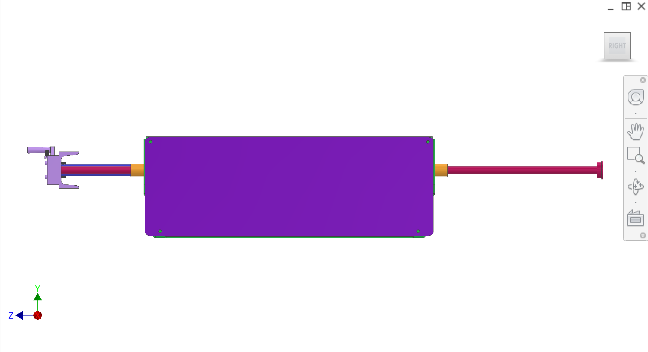
Plunger assembly, drive bracket, juice outflow — detail pages TBD. Green housings enclose spring and guide rods; interface with filter/plug-cutter and core chute.
| Colour(s) | Component |
|---|---|
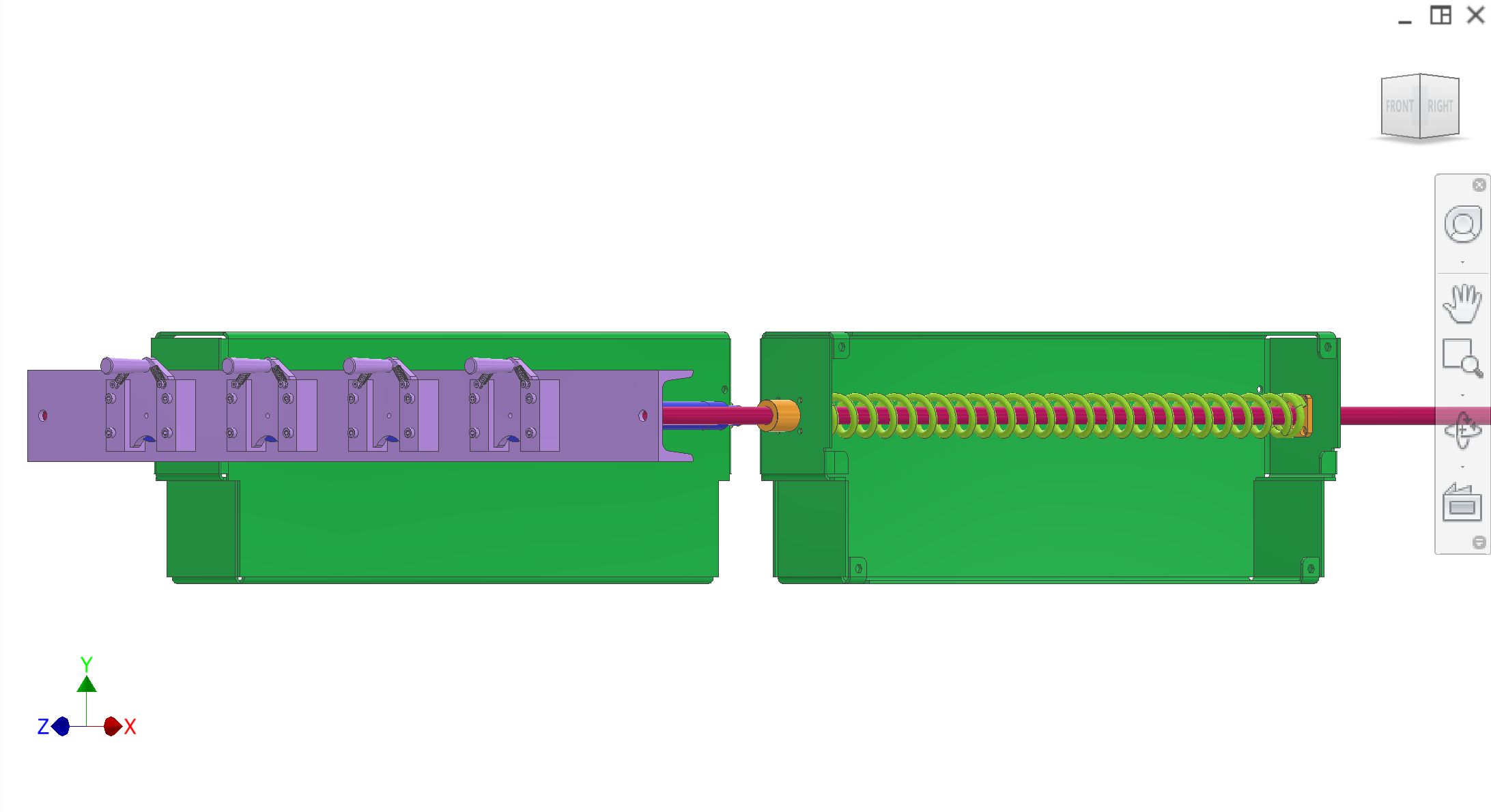
| Plunger — pushes through filter to eject core (four in parallel) | |
| Plunger drive bracket — carries plungers; connects to drive rods | |
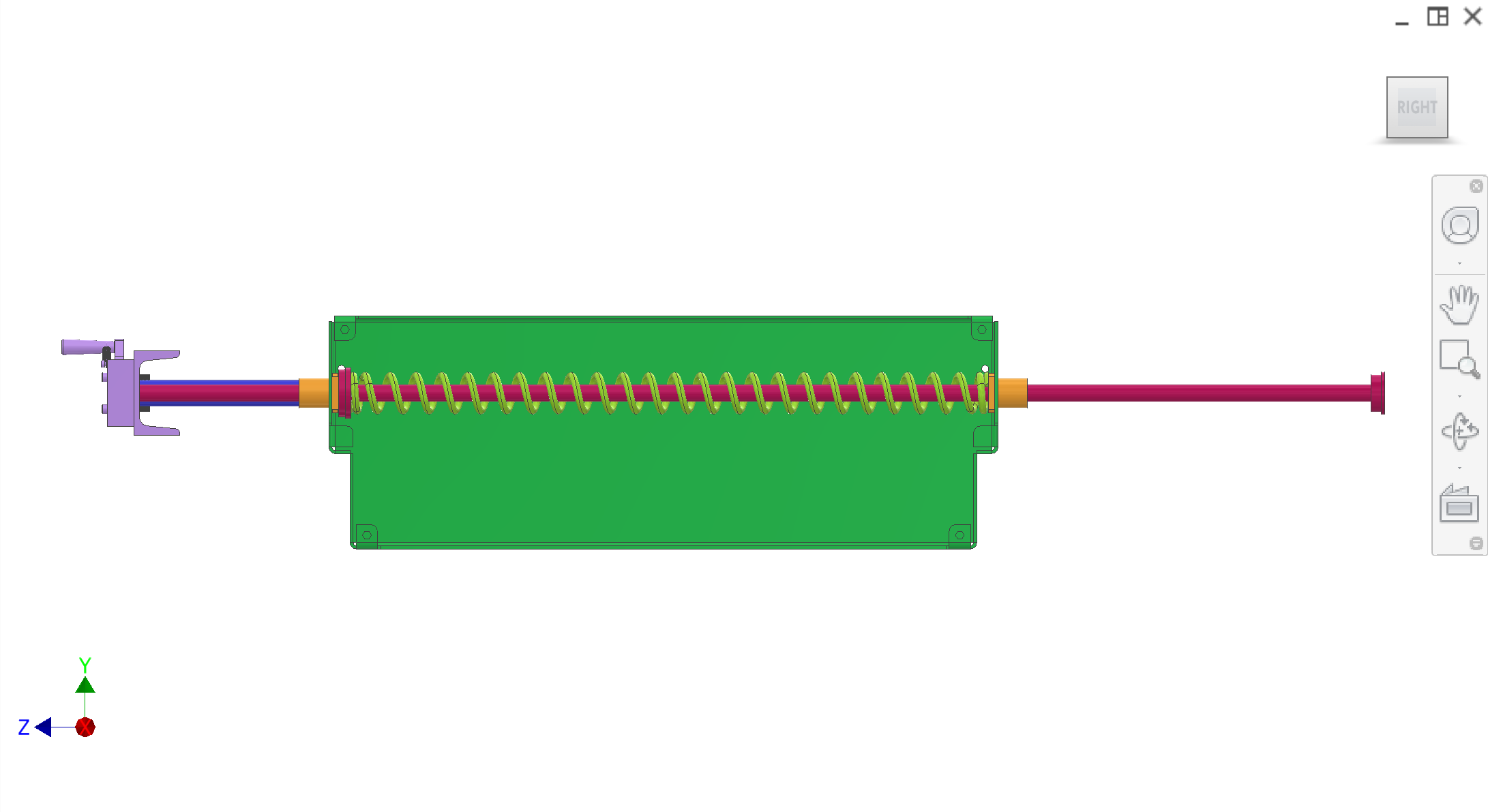
| Plunger drive rods — linear actuation; through LMK16 into green housings | |
| LMK16 linear bearing — guides rods at housing interfaces | |
| Plunger drive spring — return force; coiled around rod in housing | |
| — | Filter — plunger passes through; juice to Collection. Plug cutter — in Collection; core ejected by this system |
CAD views. Refer to figures in the text as Figure 1, Figure 2, etc.
Known interfaces and tolerances. Links go to related subsystems. Once every subsystem has an overview, subassemblies will be described in detail with how they interface with other components.
| Part | Interface / tolerance | Related |
|---|---|---|
| Plunger | Passes through filter; ejects core from plug cutter | Collection |
| Plunger drive bracket | Carries four plungers; connected to plunger drive rods; moves in unison | — |
| Plunger drive rods | Slide through LMK16 linear bearings; pass into green housings; driven by drivetrain/transmission | Drivetrain, Transmission |
| LMK16 linear bearing | At housing entry/exit; guides plunger drive rods | — |
| Plunger drive spring | Coiled around rod in green housing; return force | — |
| Core (output) | Falls into core chute after ejection | Disposal system |
| Filter / plug cutter | Housed in collection; plunger interfaces with same station | Collection |