Yoke track geometry, shaft parallelism views, pull-bracket / rod stopper engagement, and top-cap concept. Design discussion and tolerances remain on Yoke and drive shafts.
Introduction
This page holds figures only for the 35 mm shaft / yoke track region. For loading, bearing selection, and contractor questions, use Yoke and drive shafts.
Figures
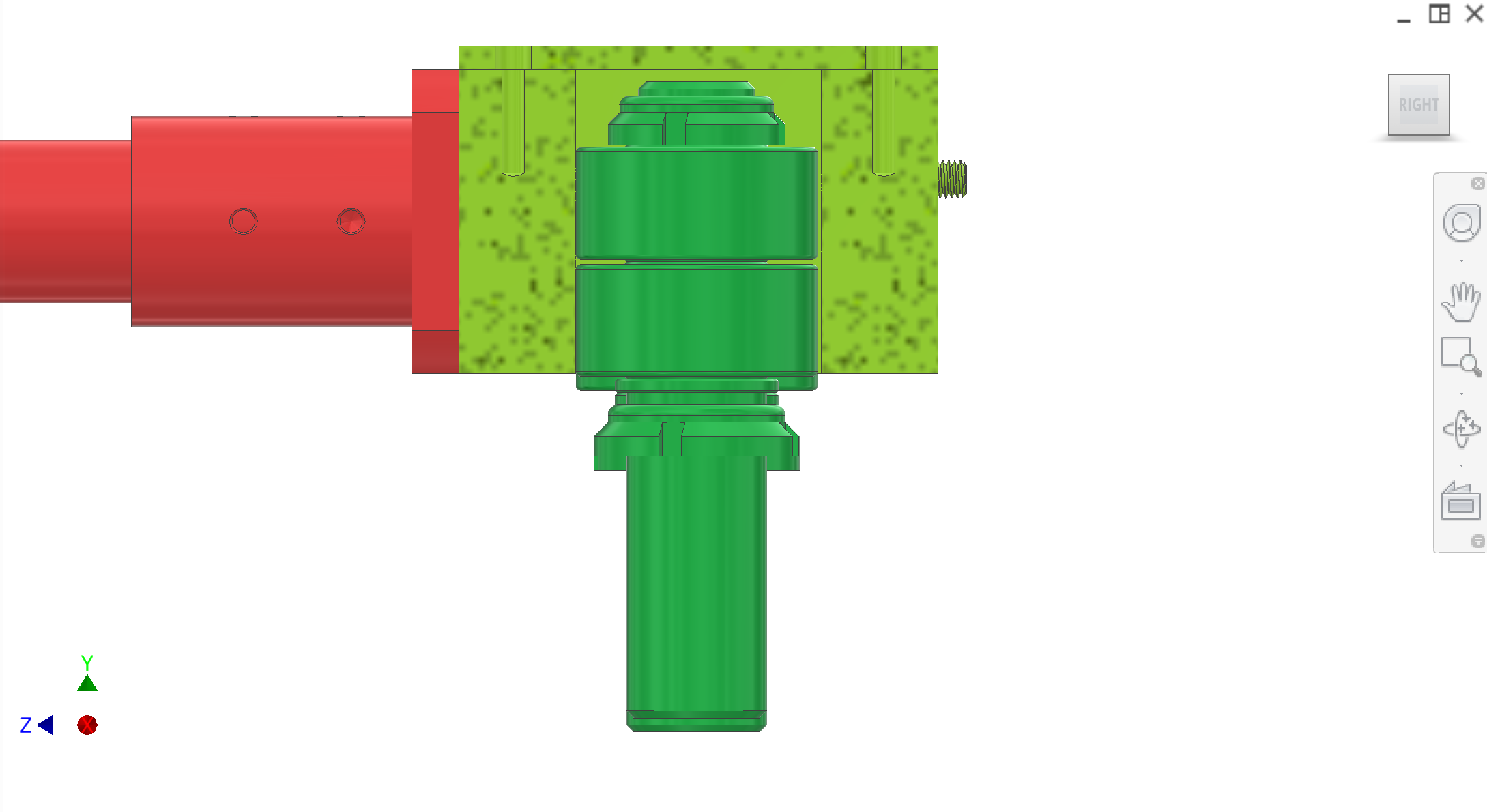
Refer to Figure 1–Figure 4. (Filename parralelism2.png is as provided in the repo.)
Figure 1. Yoke cam track — side view.
1 / 4
Recommended figures (contractor clarity)
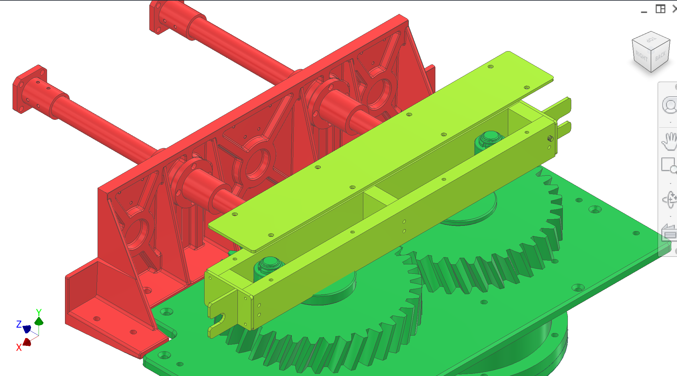
Add figure: Bearing / shaft stack — exploded or section showing LMF/LMK mounts, shaft shoulders, and scraper/cover gap.
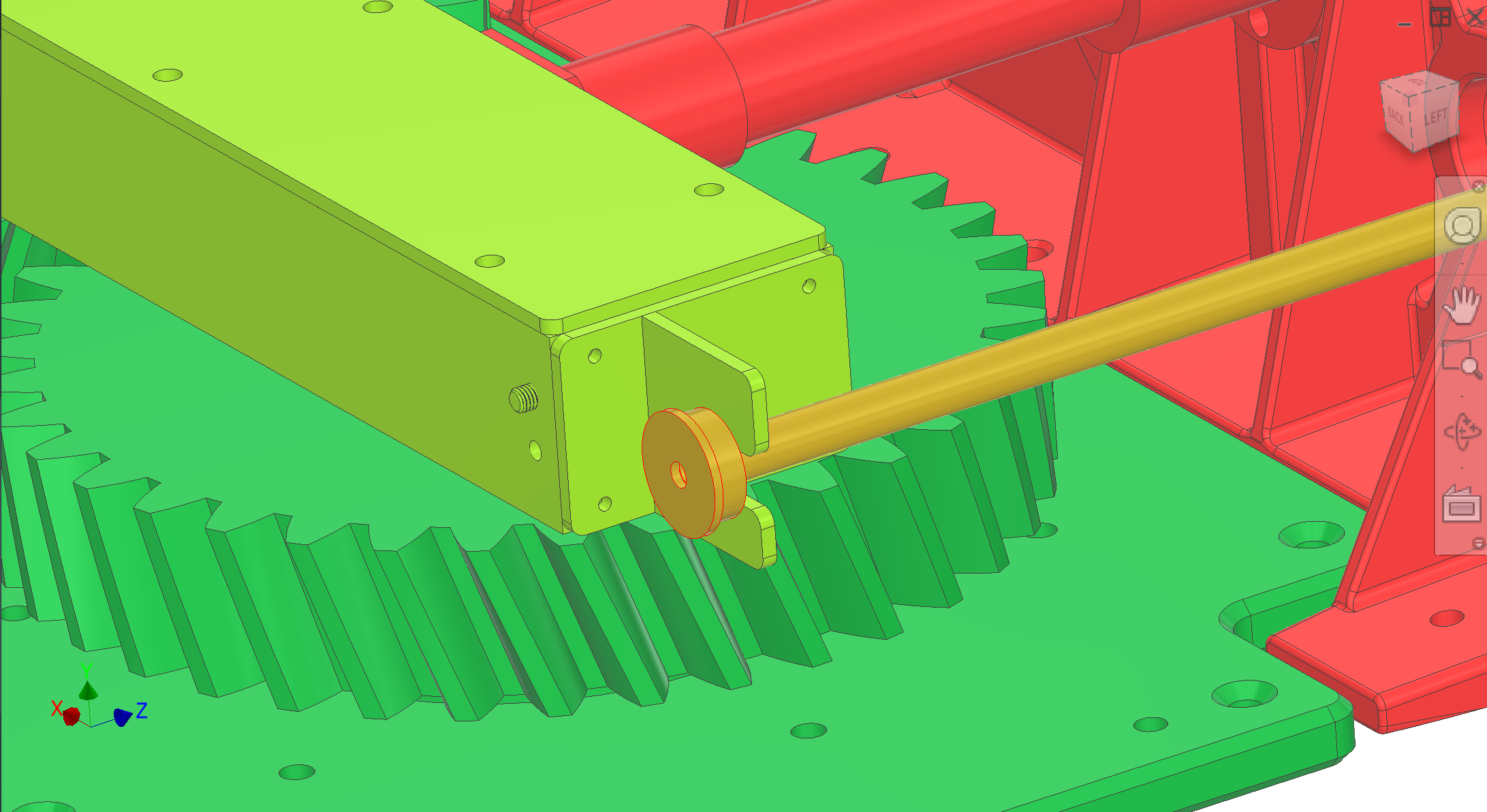
Add figure: Pull bracket + rod stopper — clearance and engagement depth through full return stroke (supplement Figures 3–4).