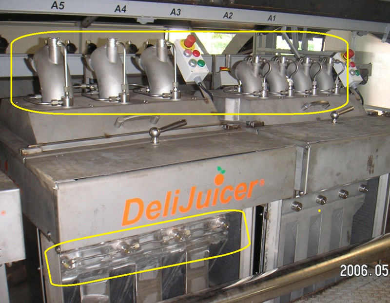
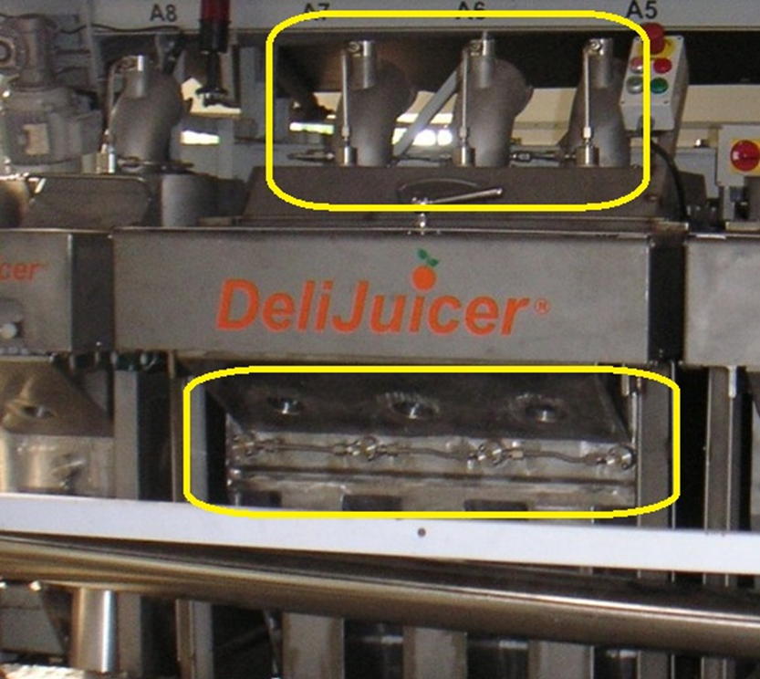
Part of the Clean-in-place (CIP) section. Nozzle layout + rigid stainless manifolds + flexible hose interfaces to the plant CIP line.
Introduction
This page captures the spray nozzles that clean the interior of P6 and the piping strategy connecting them to the plant CIP system. There are 21 nozzles in total, organized into a Fruit intake system lid group (12 nozzles, one CIP port in each 90° feeding tube) and a peel-deflector group (9 nozzles below peelers). Each group connects through rigid stainless pipes to a single input, with flexible hoses to allow the feeder to open/close. The juice collection circuit is cleaned separately via counter-flow backflush (see Third-party CIP control).
Colour key & components
Components to define (colours may vary across CAD figures).
Colour(s)
Component
—
Spray nozzles — 21 total; mix of circular-jet and angled-jet locations per station.
—
Rigid stainless piping — manifolds connecting nozzles to single input connection per group.
—
Flexible hoses — connect manifold groups to plant CIP line while allowing feeder to open/close.
Figures
CIP nozzle layout and feed pipe routing (photos/CAD snapshots).
Add figure: Labeled photos — nozzle groups A–E on at least one built station (not only schematic crops).
Add figure: Manifold / hose routing diagram — rigid pipe + flex loops with feeder hinge open vs closed.
Add figure: Spray coverage sketch — cone/angle overlay on feeding tube and peeler targets for cleaning validation.
Discussion
Nozzle locations (per P6 concept)
Locations A–E correspond to the CIP spec. Exact nozzle models, spray angles, and flow rates are TBD and must be validated by cleaning tests.
A (feeder curve, circular jet) — one nozzle per feeding tube, aimed into the curved section (tube turned backwards).
B (behind feeding tube, angled jet) — one nozzle per peeler aimed at the movable peeler around mid-stroke.
C (front of feeding tube, angled jet) — one nozzle per peeler aimed at the fixed peeler.
D (rear plate of peel deflector, angled jet) — one nozzle per peeler aimed at the movable peeler (mid-stroke); mounted below peelers. Spray reach must clean surfaces behind/around the driven chute deflector that covers core chutes during compression.
E (front plate of peel collector, angled jet) — one nozzle per peeler plus one additional nozzle (total 5) positioned between core ducts and at both sides, avoiding deflector hardware (updated concept: deflectors are primarily driven/under-peeler).
Nozzle counts
Total: 21 spray nozzles
Feeder lid: 12 (4 stations × 3 nozzles per station: A + B + C)