Over-center hinge linkage used to keep covers closed during operation and open for service/access; designed for folded/welded sheet metal with spring assist.
Introduction
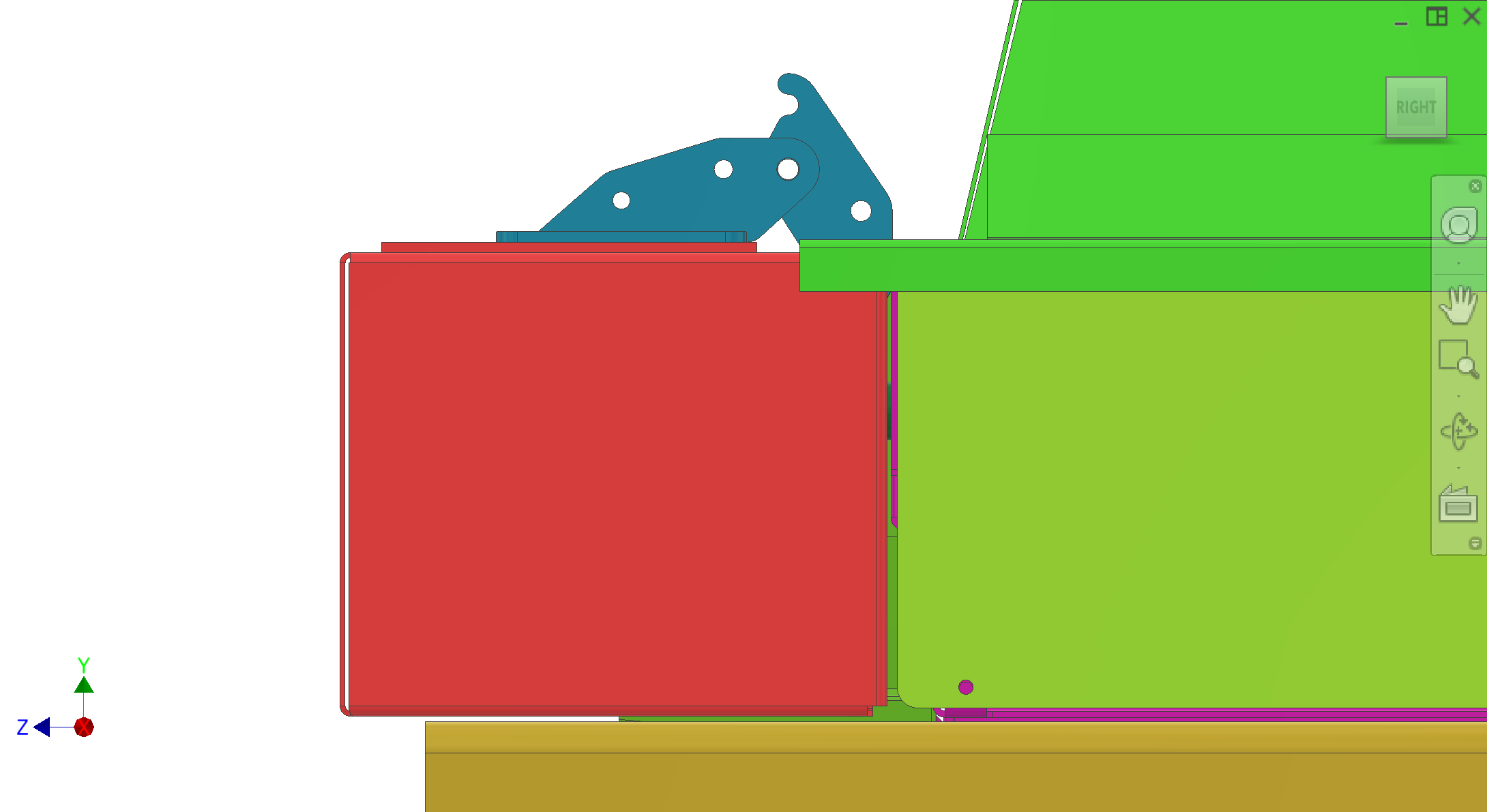
Overcentered hinges are the mounting mechanism within the Enclosure / shell subsystem used to attach the feeder lid, drivetrain shell cover, and plunger-side cover to the frame. The hinge geometry provides a stable "open" position (stays open for service access) and a stable "closed" position (stays shut to protect operators during operation). Springs bias the linkage so it naturally stays in either position, and the hinge brackets interface with stiff backing plates rather than thin cover sheet.
Colour key & components
Hinge components: mounting bracket, pivot/pins, latch/stopper feature, and spring mounting points.
Colour(s)
Component
—
Hinge bracket / arm — sheet metal welded plates and dowel-based pivot features.
—
Stopper + latch — positions the linkage at open/closed over-center positions.
—
Spring mounts — hole locations support spring placement (either side).
Figures
Reuse existing enclosure hinge views (until hinge-specific CAD figures are added).
Figure 1. Overcenter hinge assembly concept.
1 / 1
Recommended figures (contractor clarity)
Add figure: Hole pattern detail — pivot, latch, and spring holes with tolerances.
Add figure: Open vs closed over-center — linkage angles and spring line of action.
Add figure: Backing plate / stiffener — how hinge loads enter frame or cover shell.
Discussion
Components
Pivot hole — the first hole closest to the mounting surface defines the pivot point.
Stopper/latch hole — the next hole creates a latch engagement as the arm rotates over-center.
Spring mount hole — final hole contains indents such that springs can mount on either side.
Dowel + spring retention — hinge parts may be formed from welded sheet metal plates and use dowels/pins to locate features and springs.
Interfaces
Input: cover mass + user-open/close forces and spring reaction.
Output: stable open and closed positions for covers; repeatable engagement for safety interlocks.
Mount: hinge mounting to bracing/backing plates so thin covers remain stiff.
Interfaces and tolerances
Hinge hole locations, stopper geometry, and spring strength must be tuned so the cover stays shut under vibration and washdown forces, and stays open for service.
Part
Interface / tolerance
Related
Over-center geometry
Stopper/latch locations must be robust; spring must hold closed when latched
Spring placement must support open-stay-open and closed-stay-closed over-center conditions
—
Known issues & risks
Welding vs forming — owner intent is to investigate a simpler folded-sheet geometry to reduce welding and improve manufacturability; current hinge design details are WIP.
Spring strength + hole location — not finalized; must be tuned by prototype testing and should be repeatable across builds.
Questions for contractor
Propose a manufacturable overcenter hinge design (folded/welded) that meets washdown robustness and repeatable open/close positions.
Define spring selection and how hinge geometry tolerances affect open/closed stability.
Recommend anti-corrosion materials/finish suitable for food splash and cleaning chemicals.