Single reference for the P6 industrial prototype and RFP structure. Last updated: 2026-03-20.
The P6 is the newest generation citrus juicer in the Delijuice line. It is designed to handle a wide range of citrus varieties (including lemons) with a repeatable, industrial extraction cycle that separates juice from waste streams.
The program is setting up a pilot production environment in Jiangxi (China) with target setup in October. The first machine to prototype and validate is the P6-870; the P6-970 with 3x larger extraction modules is planned later.
P6-870 throughput: ~280 fruits/min, producing an estimated 1360 L/hr of juice. A pilot line is envisioned with 6 extractors in series to reach ~8160 L/hr, so all downstream third-party equipment must be sized to that total capacity.
The P6-870 is designed to integrate with existing industrial orange juicing lines and can be substituted for JBT Marel–style machines built by Kaiyi or similar line providers.
What P6 is
P6 is the current industrial prototype citrus machine built around the Delijuice extraction cycle (same functional sequence as prior Delijuice industrial extractors). Machine lineage: P3 → P4 → P5 → P6 (today’s development focus). The P6 program is being prototyped in collaboration between Delijuice and YES Machining (fabrication). The smaller 323 / countertop line is a separate product family—not the subject of this RFP.
Jiangxi (JX): Factory with LTA (Long Tai An). Miniplant target: 8,160 L/h, 6 extractors, turbo-filter, pasteurizer. Operations pressure: October.
Drawings / fab target:15 May for YES to fabricate (Shenzhen area).
How the machine works
Delijuice extraction cycle (high-level)
Fruit intake — citrus is staged one-at-a-time and presented to the extraction cavity.
Compression — fruit is compressed/peeled; juice is routed through the filtration/collection path.
Juice outflow — juice flows into collectors and then to tanks/pasteurisation equipment.
Core expulsion — a plug/core is ejected and routed to the core waste chute/auger.
Factory product flow (citrus → juice → pasteurisation → filling)
Upstream → P6 → tanking → downstream. Third-party sorting and feed bring fruit to the P6 entry tubes; P6 outputs juice to plant tankage; peel and cores go to separate auger lines.
Third-party sorting + feed — Pre-sorted, pre-washed citrus through a size sorter into P6 feed lines and entry tubes.
P6 extraction — Staged fruit is peeled/compressed; juice through filtration/collection; peel and core to separate waste chutes/augers. ~1360 L/h per extractor; planned 6× line ~8160 L/h.
Juice tanking — Juice from collectors into juice tanks sized for total line rate.
If the diagram does not render, enable JavaScript; the sequence is also listed in order under the chart.
flowchart LR
  A[Size sort + feed] --> B[P6 extraction]
  B --> C[Juice collectors]
  B --> W[Peel + core augers]
  C --> D[Juice tanks]
  D --> E[Paddle finisher]
  E --> F[Holding tank + agitator]
  F --> G[Tube-in-tube pasteuriser]
  G --> H[Cooling tank]
  H --> I[Filling]
  I --> J[Refrigeration]
Downstream sequence (same as diagram): paddle finisher → holding tank (agitator) → tube-in-tube pasteuriser → cooling tank → filling → refrigeration.
Top-level assemblies
Each subsystem has its own RFP section with photos, Q&A, and part/parameter details. The legend below lists all 11 subsystems with their CAD colour(s) and a short description.
Driven assembly that works with the fruit intake line: stages fruit, drives peelers/sync motion, and drops one fruit at a time into the juicing chamber (collection side).
Intake line and feeder body: brings fruit in and releases one orange at a time to the extraction/sync staging path (upstream of the drop into the chamber).
UI, safety interlocks, motor control/power distribution, and sensing (e.g. yoke position) that coordinate the extraction cycle.
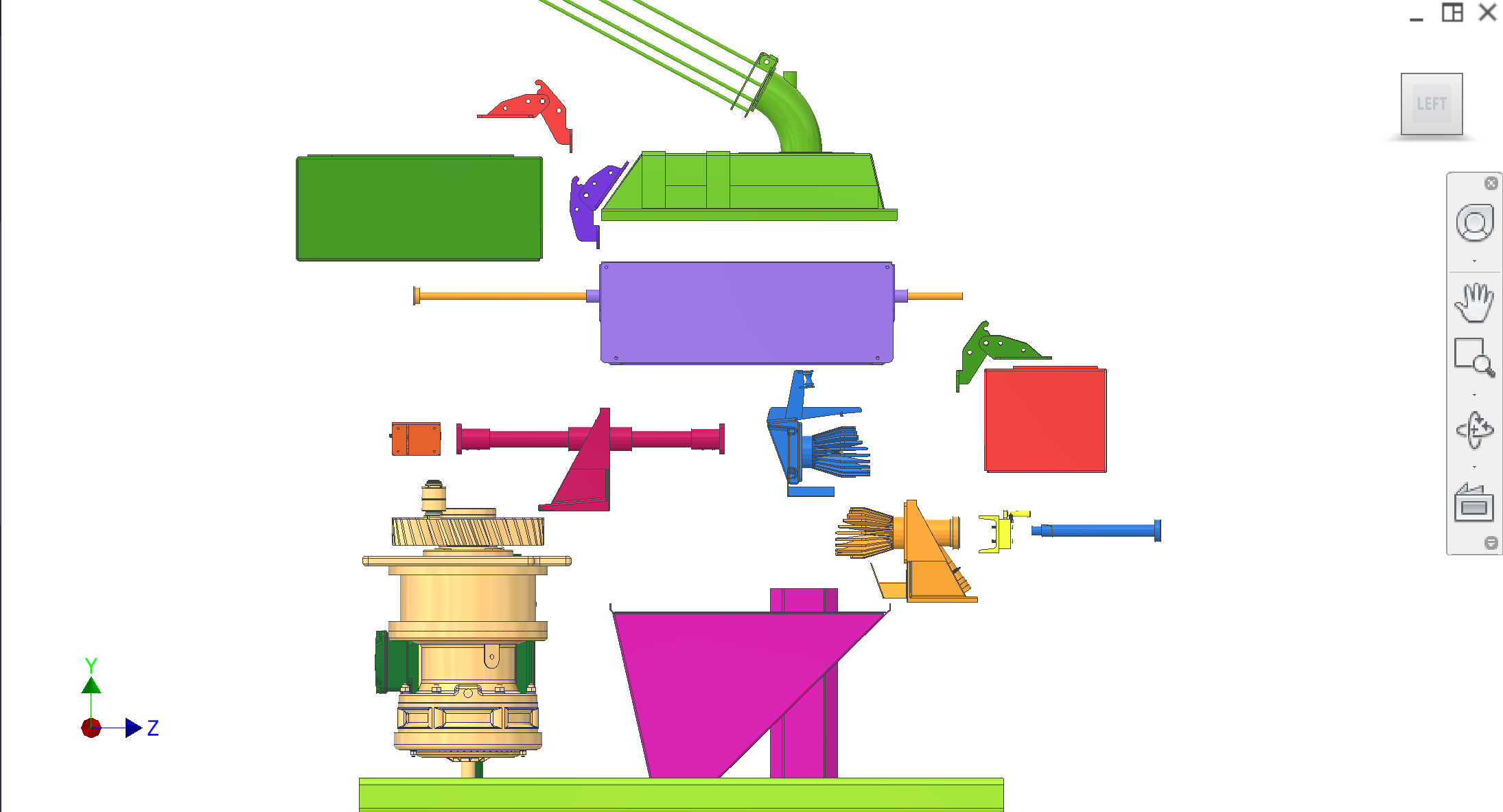
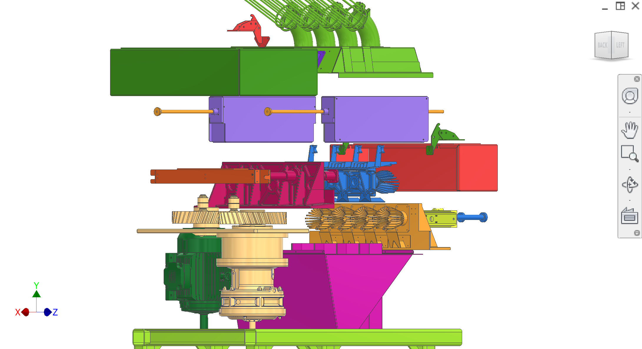
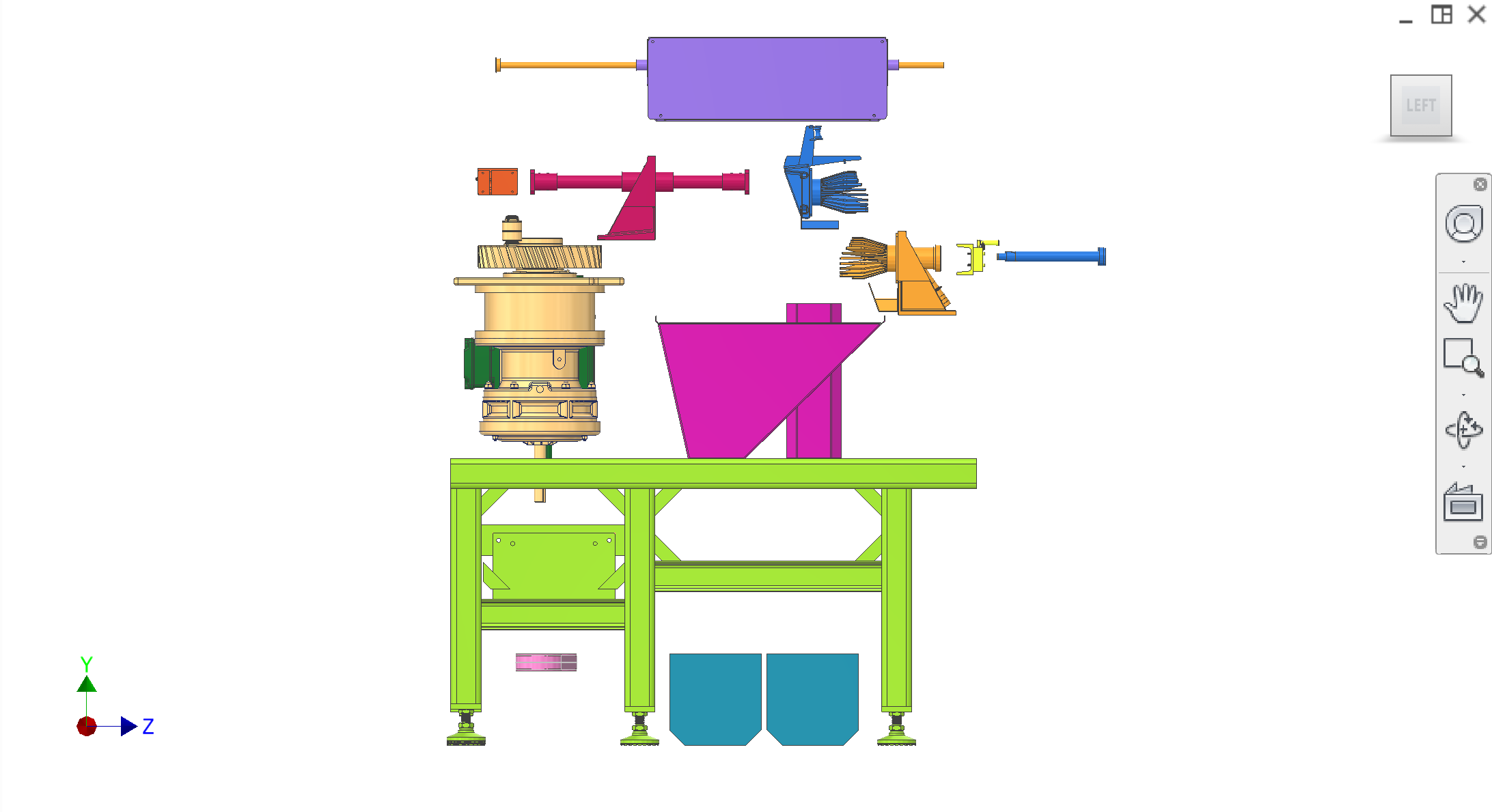
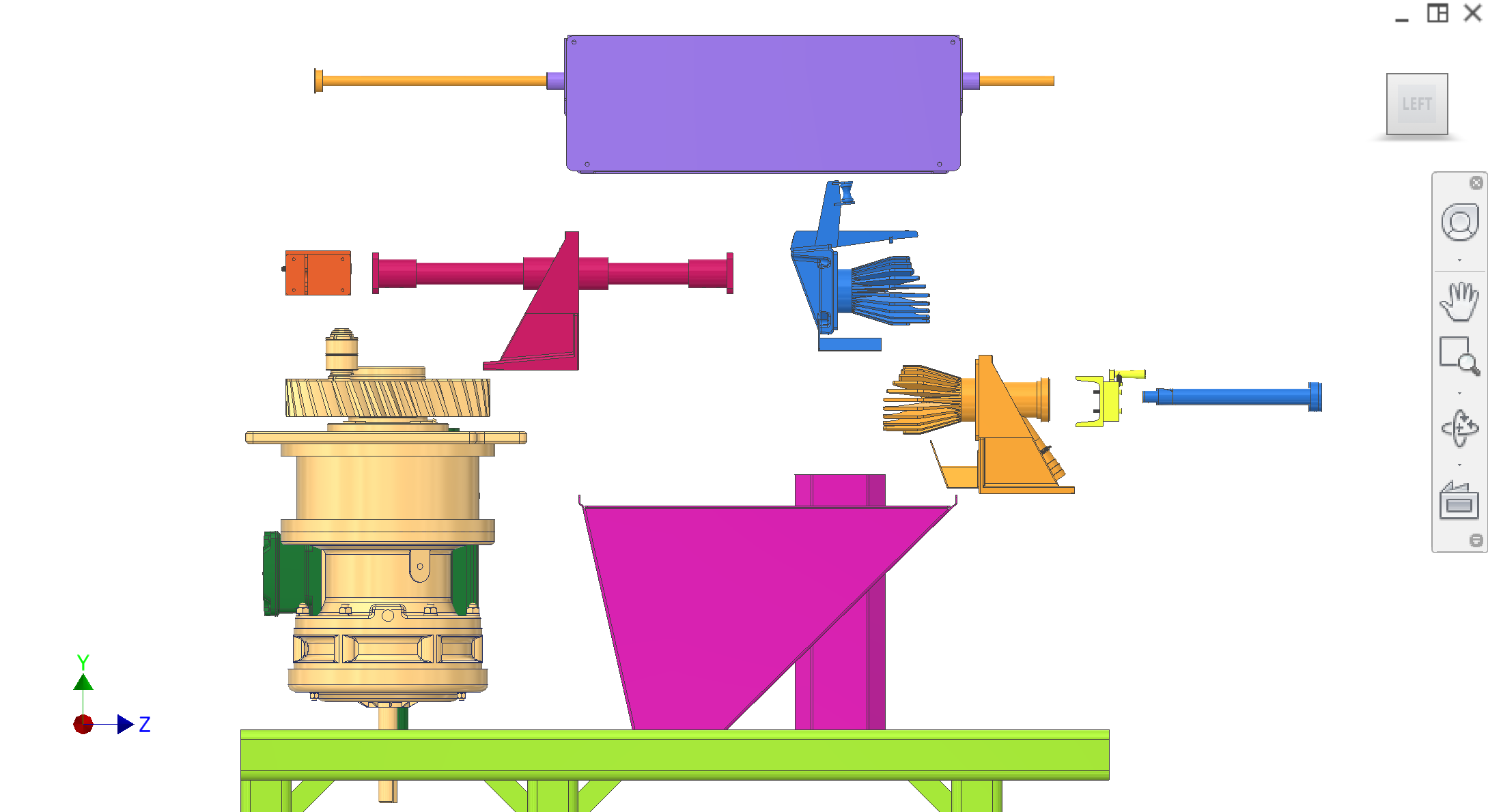
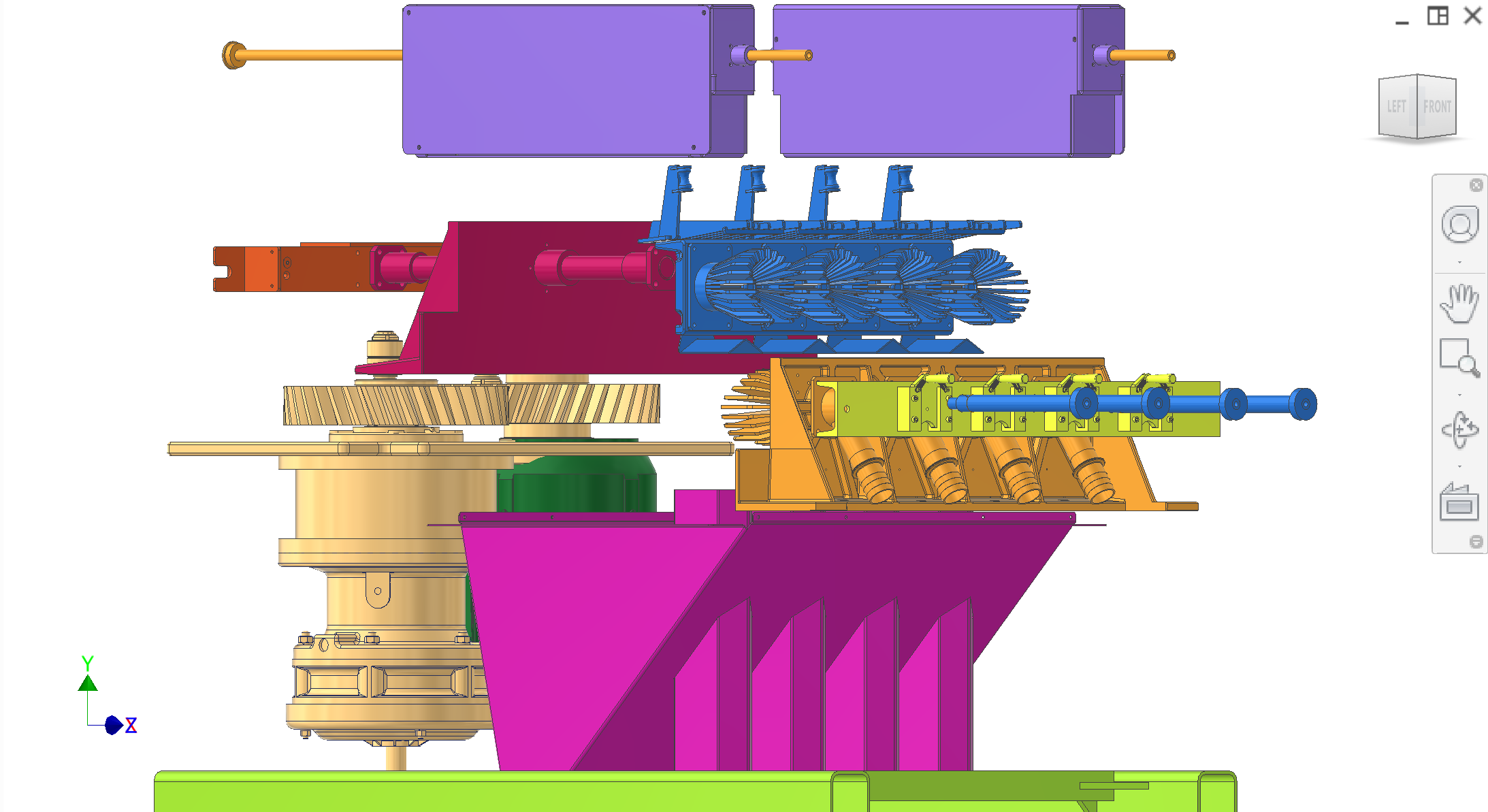
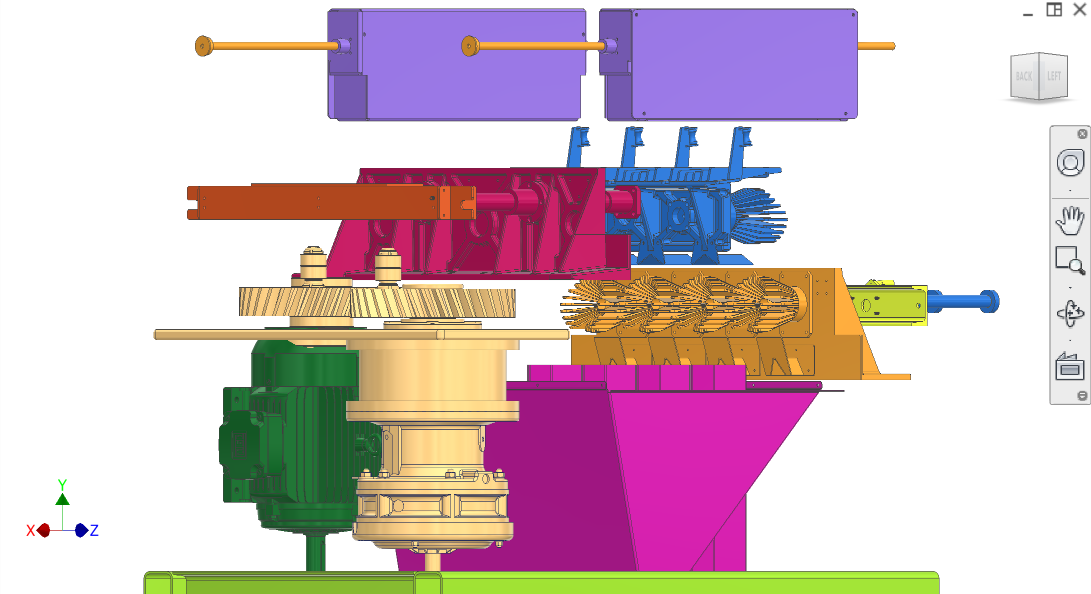
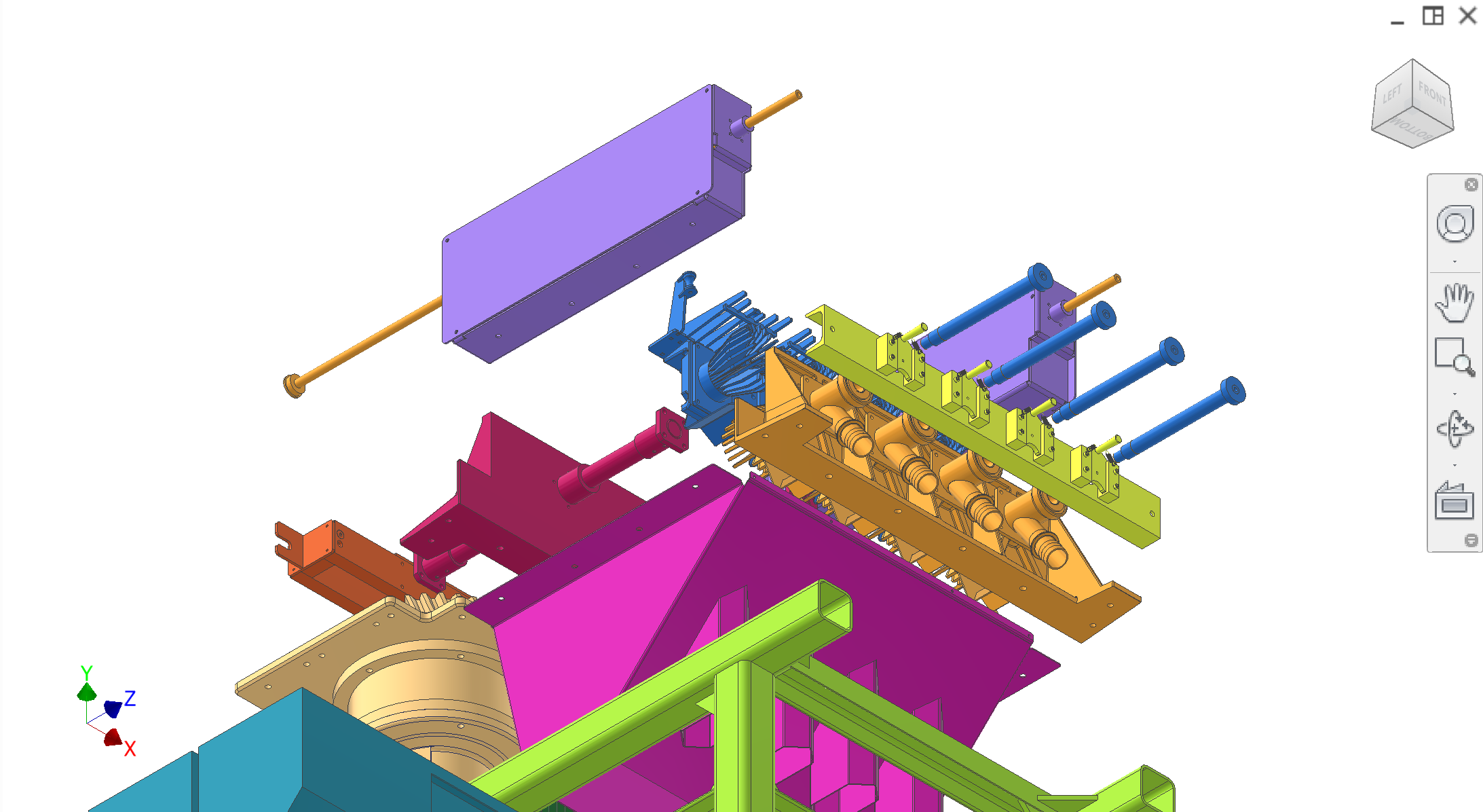
Exploded view (top-level assembly)
Exploded CAD sequence for the full machine. Assembly-step and subsystem close-up figures remain on the Frame page.
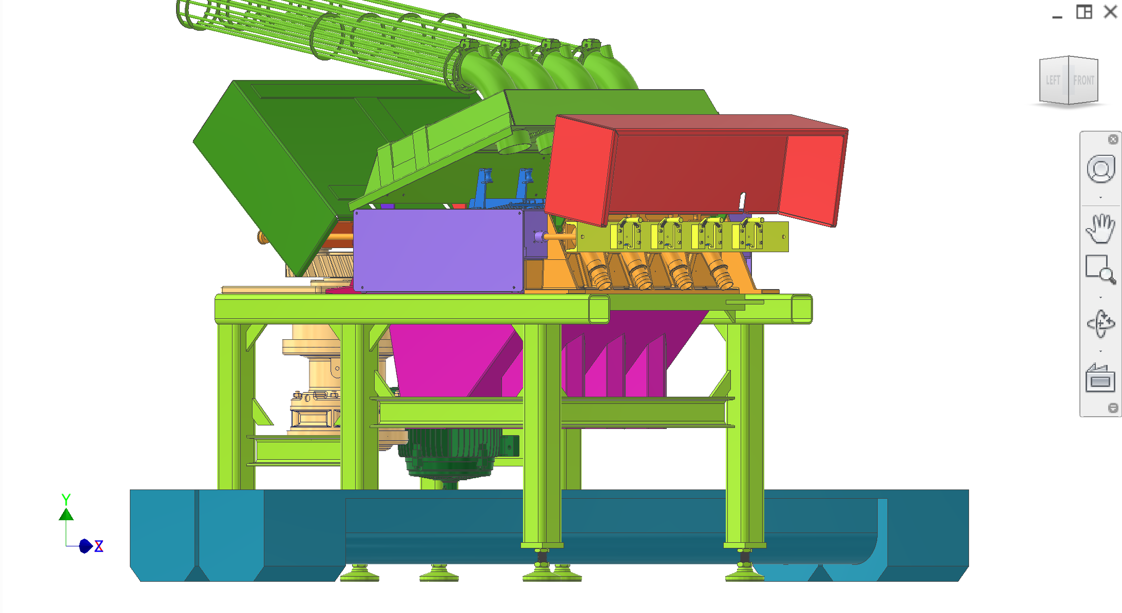
Figure E1. Top-level assembly — exploded (step 1 of 7).
1 / 7
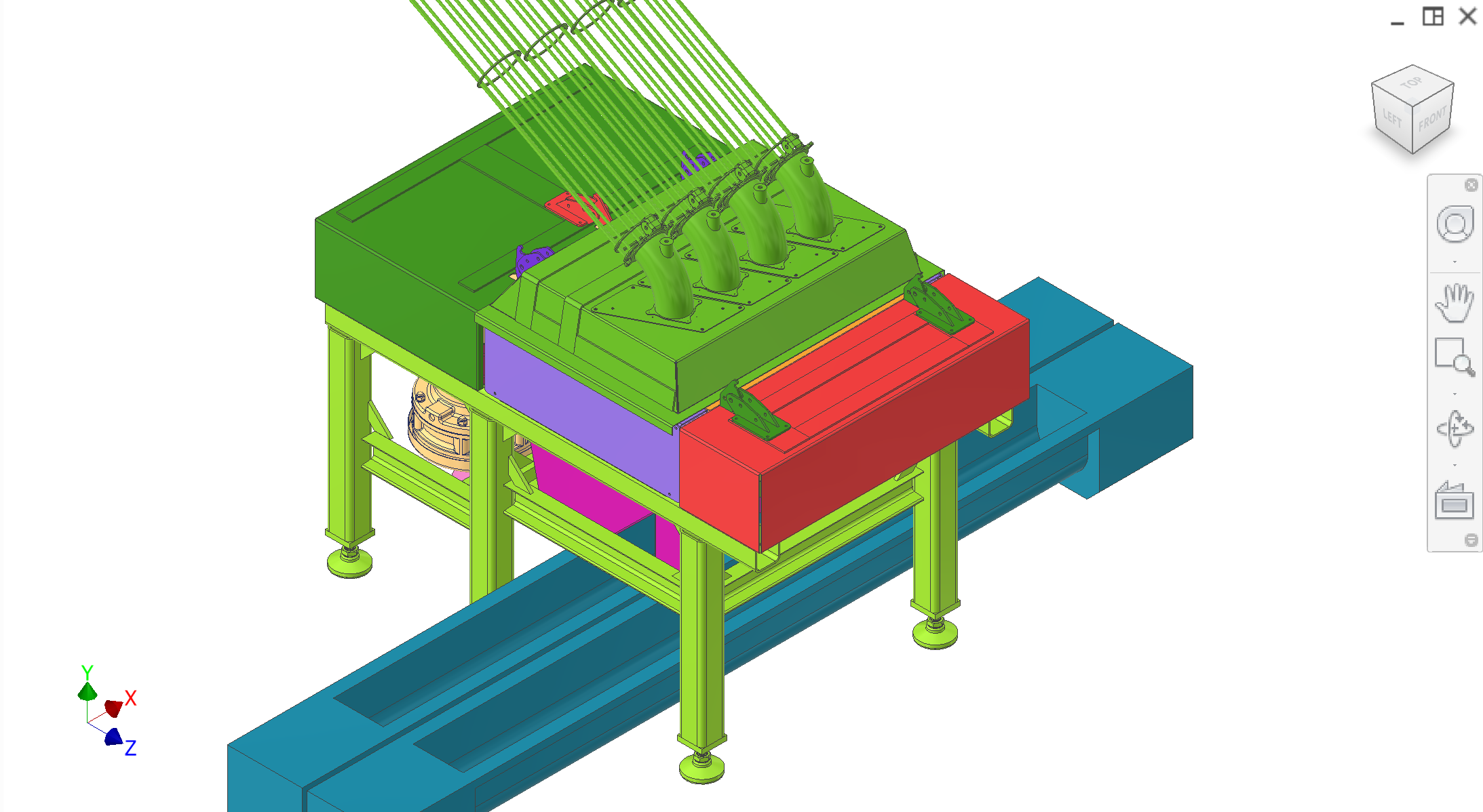
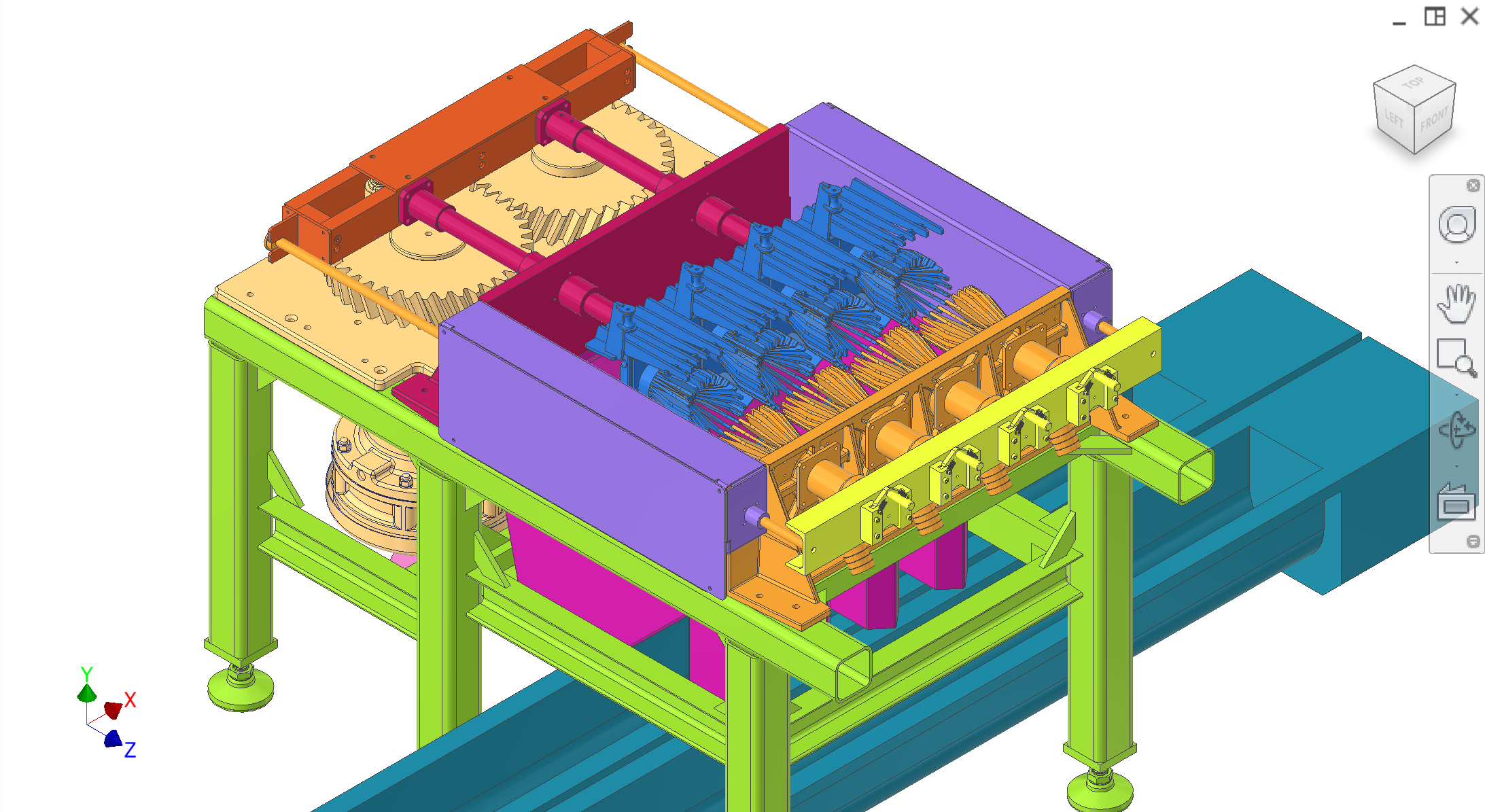
Assembled views
Top-level assembly in assembled state. Figures 1–10.
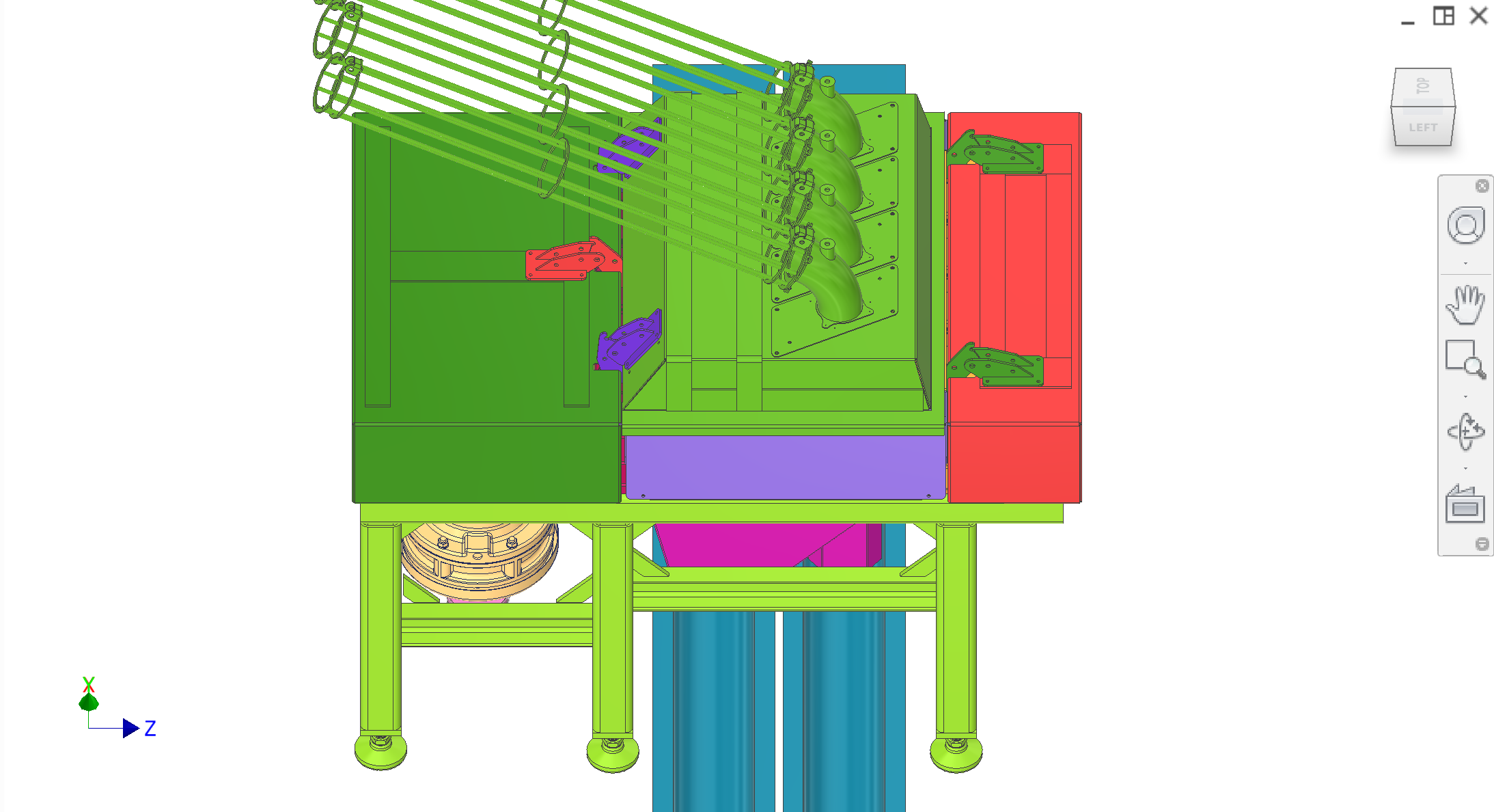
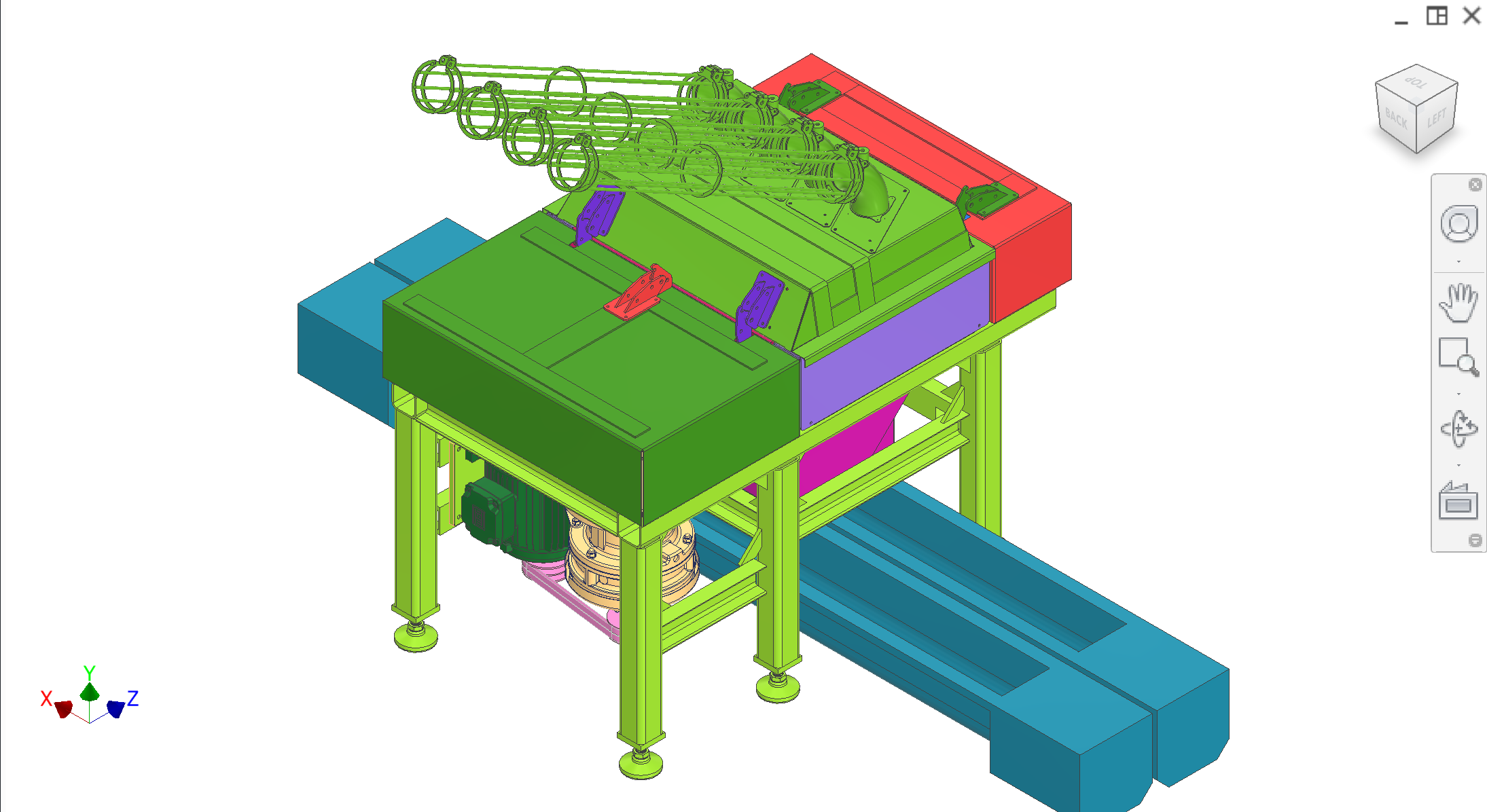
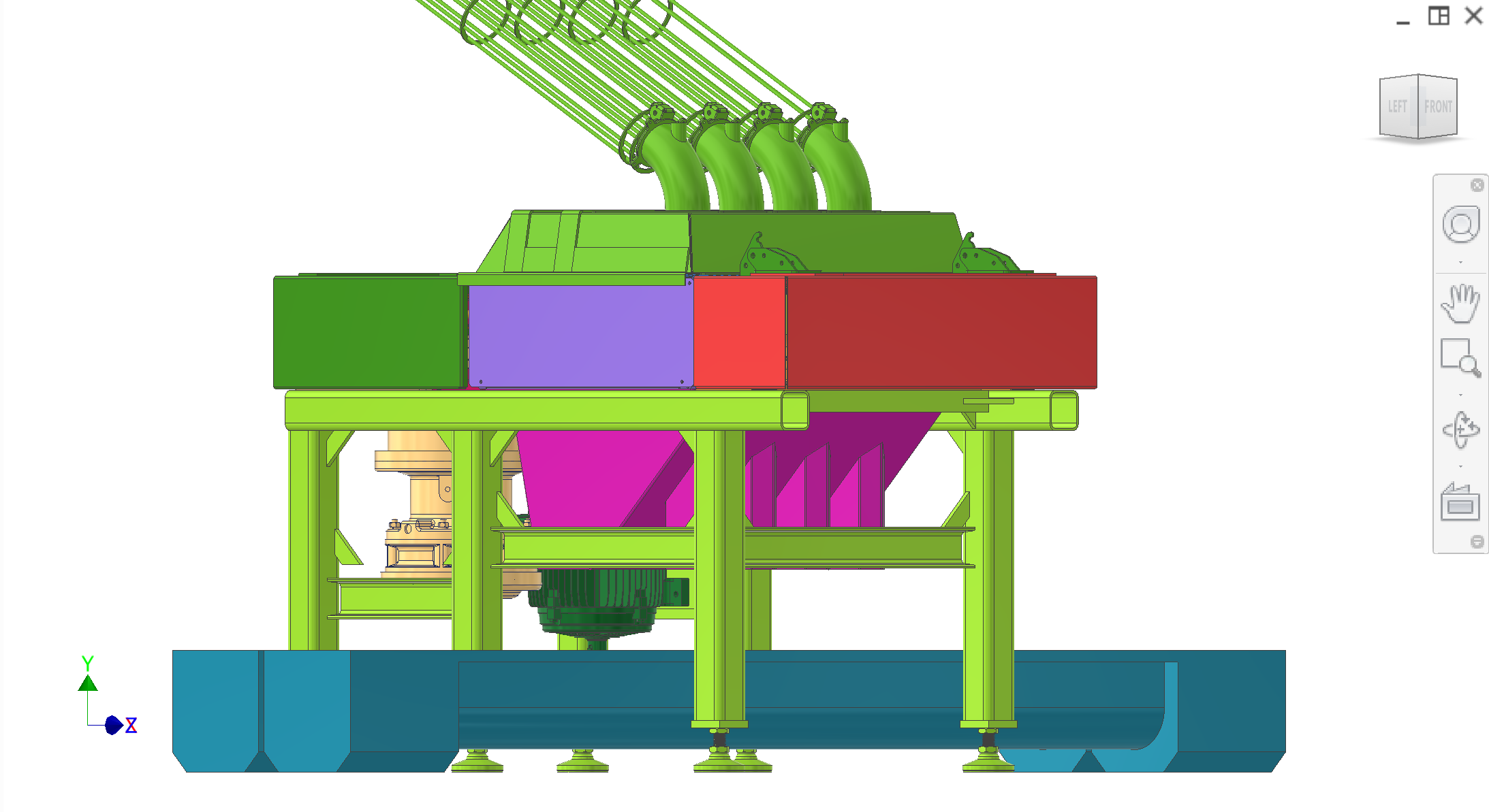
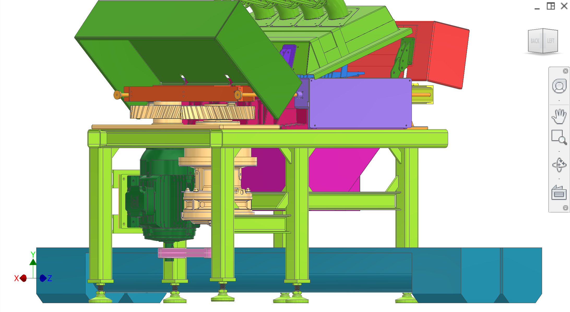
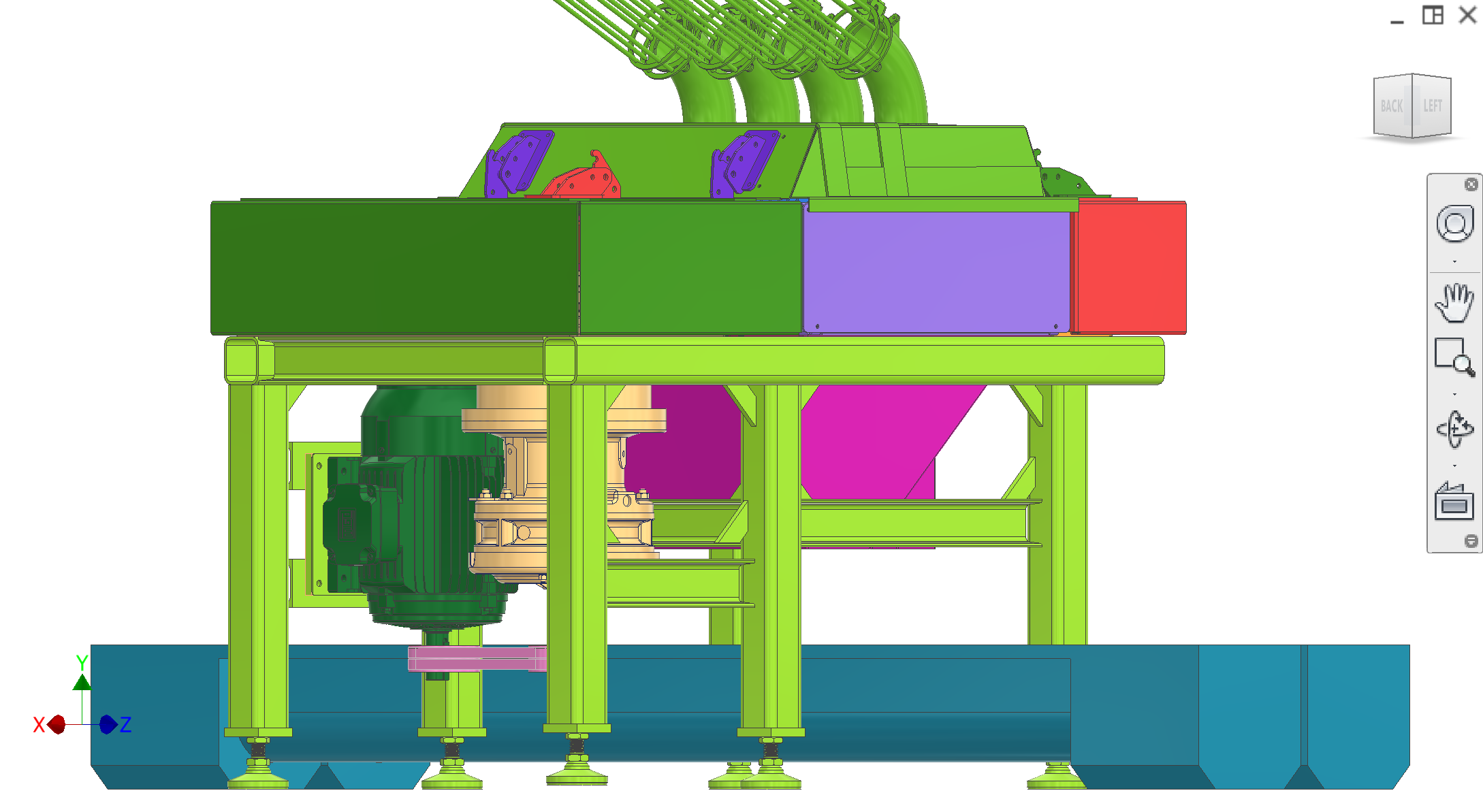
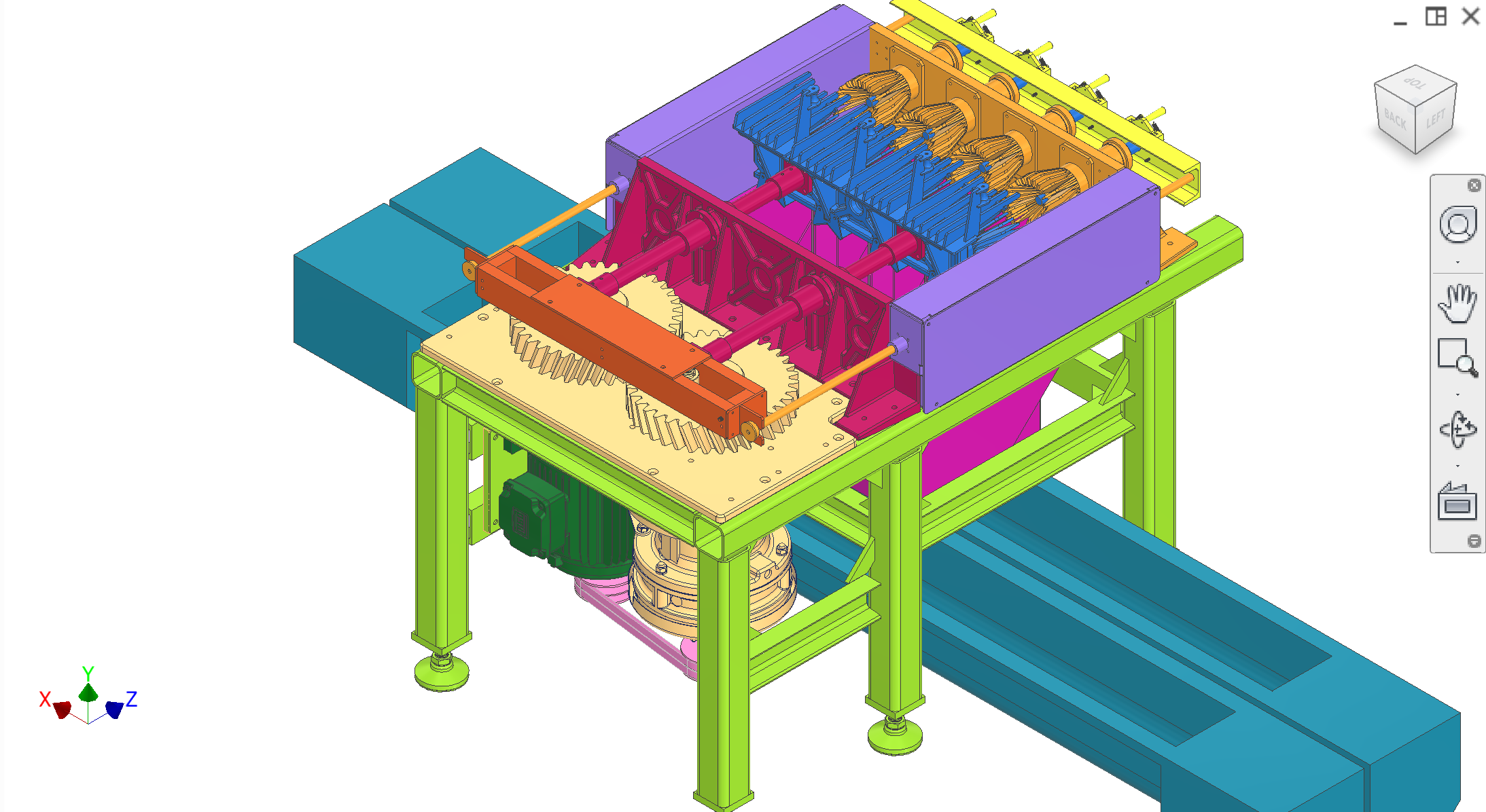
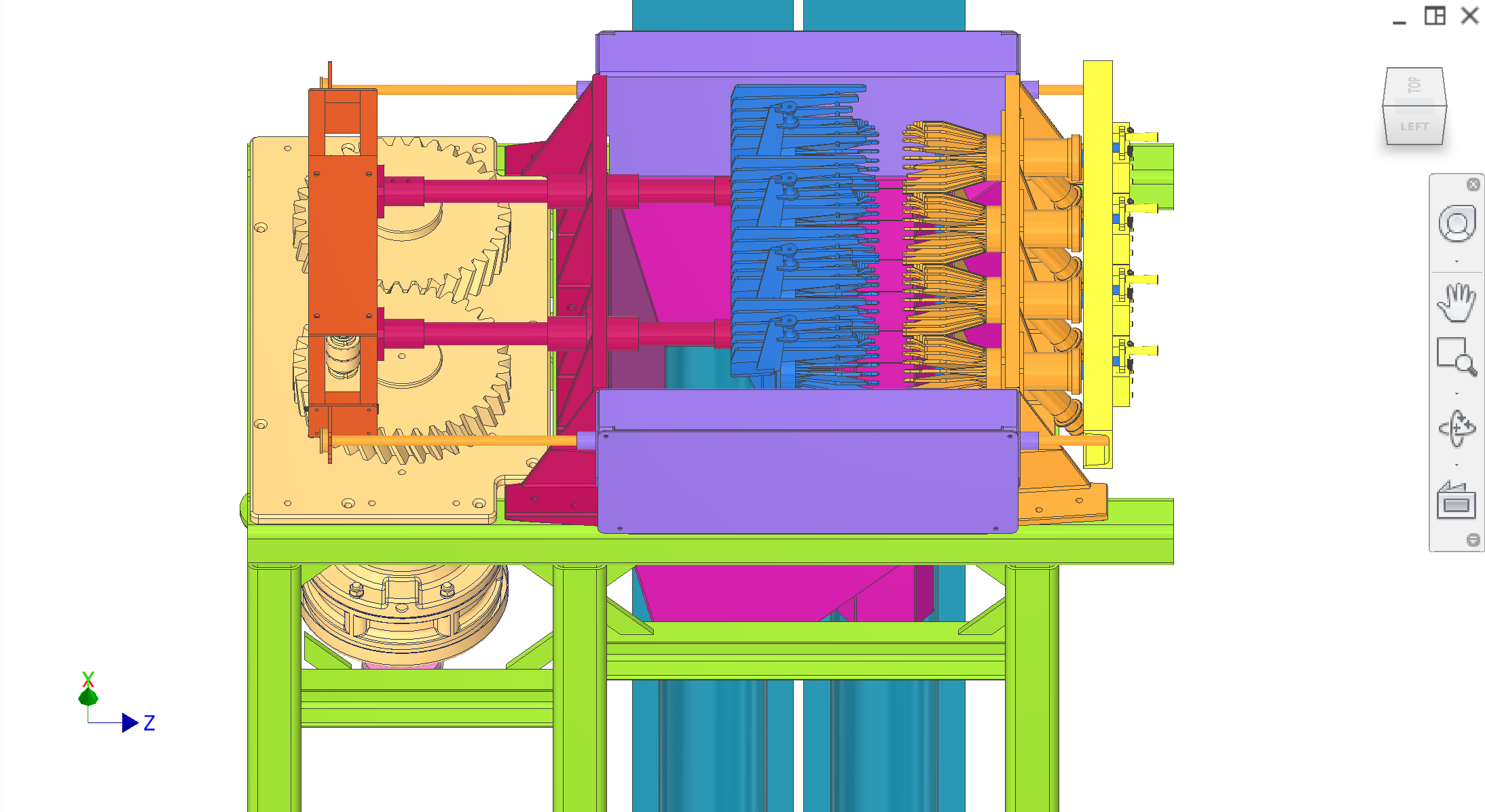
Figure 1. Top-level assembly (assembled).
1 / 10
Recommended figures (contractor clarity)
Add figure: Overall envelope — machine L×W×H and service clearances around hinged subsystems.
Add figure: Subsystem color map — single labeled photo matching the table above (for JX walkthroughs).
Add figure: Utility interfaces — electrical, CIP, and juice-out stub locations on the installed skid.
General design, manufacturing, and food-safety requirements
Materials, food safety, and surfaces
Use food-safe materials in all food and splash zones (e.g. stainless steels and compatible polymers); avoid galvanic pairs and corrosive finishes.
In food zones target surface roughness around Ra 0.8–1.6 μm so surfaces are cleanable and do not trap pulp.
Follow NSF-style guidance: no shelves, pockets, or hidden areas in food or splash zones; all food and liquid must have a defined path to drain.
Seal or weld all seams in food and splash zones so there are no capillary gaps; avoid lap joints and unsealed overlaps in these areas.
Deburr all edges; no sharp edges or burrs exposed to operators or in any zone that can collect food.
Fasteners and joints
Minimise the number of different fastener sizes; where practical restrict to M3, M5, M10, and M16 for increasing strength levels.
In food-contact areas: no exposed threads; use standoffs, weld studs, or through-bolts with nuts outside the zone. Where machine screws are required for service, hex head, Phillips, and slotted drives are acceptable; avoid other drive types in or above food zones unless agreed.
Prefer dowel pins for locating parts in shear; use shoulder bolts for joints that carry shear and rotation.
Minimise total fastener count with shared brackets and clear load paths; design for easy disassembly and reassembly for cleaning.
Design for manufacturability
Favour symmetric parts and avoid unnecessary handedness where possible.
Minimise machining and secondary processing by using stock sizes, simple weldments, and laser/plasma-cut profiles.
Specify tolerances sufficient for function; post-processing methods (e.g. grinding, honing, polishing) are selected by manufacturers to meet these tolerances.