Loads and load paths(updated 2026-03-20) — reaction loads, load paths to floor, frame CAD figures gallery.
Introduction
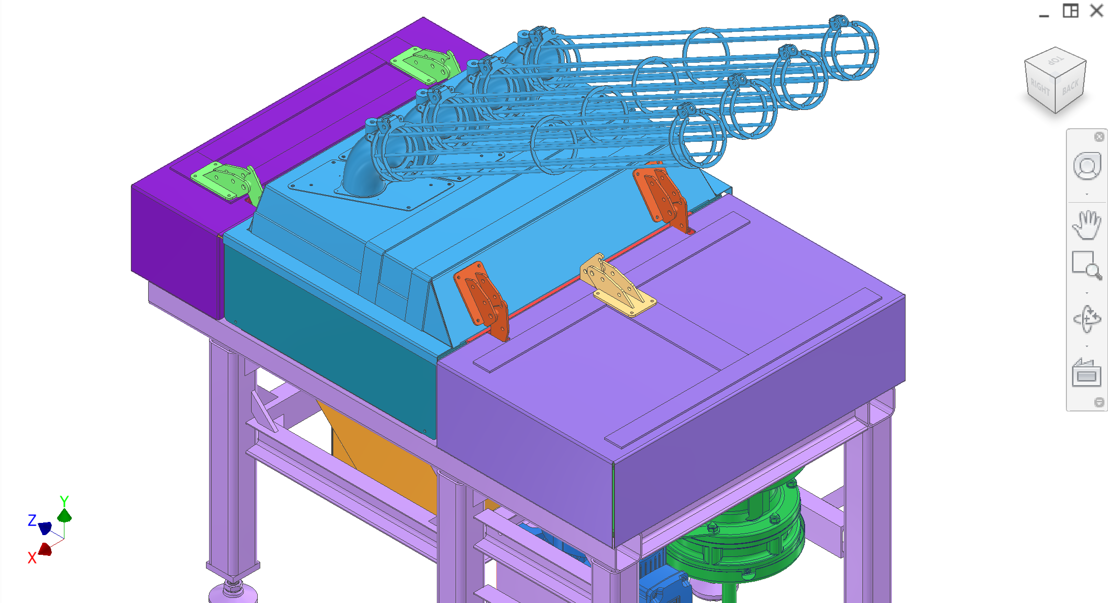
The frame is the primary welded structure and datum for alignment. All subsystems mount to it. Design focus: stability, alignment, force transmission, and repeatable, easy assembly. The three main loaded plates are the collection (loaded) mount plate, transmission mount plate, and drivetrain mount plate—everything else hangs from a top-down assembly sequence onto those interfaces. Detail below expands assembly order, construction, and contractor questions.
Colour key & figures (how subassemblies fit together)
Assembly steps and subsystem closeups. The exploded top-level assembly slideshow is on Project overview. One colour key below applies to all figures in this section.
Colour key (all figures)
CAD colour key for the top-level assembly. Each subsystem links to its RFP section.
Top-down workflow intended to stay repeatable after service teardown. Figures A1–A5 illustrate the sequence; captions stay short—use this list for the full intent.
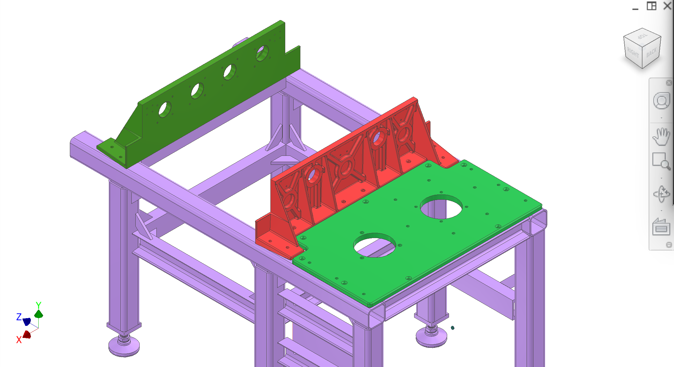
Level and plate the interfaces. Set frame height on the six leveling mounts. Locate the three main mount plates (collection/loaded, transmission, drivetrain) on the side rails and cross beams using bolt holes, shims, and flatness checks. Align, clamp, then drill and ream for H7 dowels where the datum scheme requires it (see Construction). Figure A1.
Yoke and extraction/sync. Install the yoke and extraction/synchronisation module on the transmission/drivetrain shafts. Figure A2.
Plunger drive. Lower the plunger drive system between the plates; connect yoke to plunger rods/bracket. Figures A3–A4.
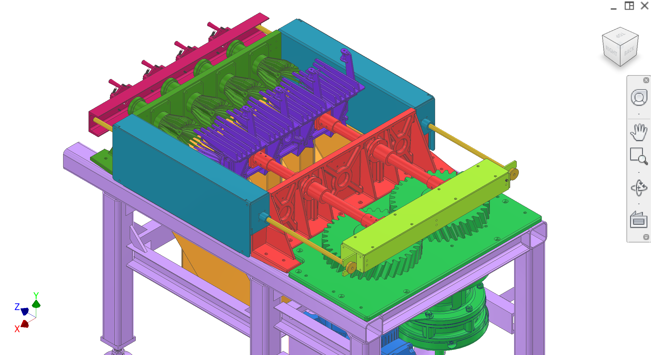
Enclosure and feeder. Mount overcenter hinge covers/shelves and attach the feeder from the top; verify latch/interlock and clearances. Figure A5.
Peeler and shaft alignment should be established once (adjust → lock), then held with align-then-drill/ream doweling / shoulder-bolt indexing so rebuilds do not lose concentricity.
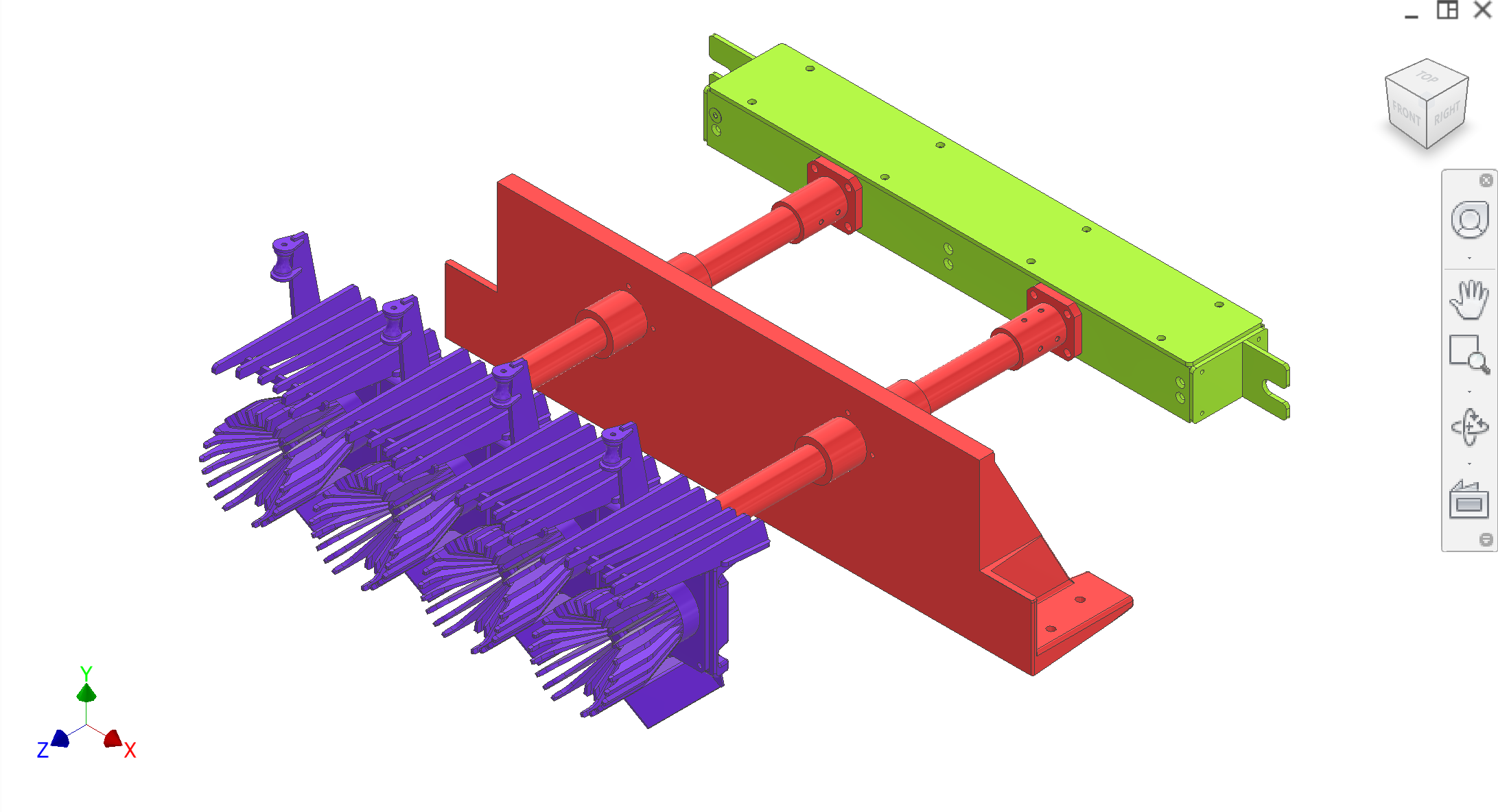
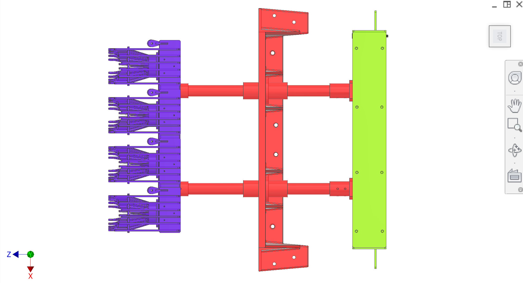
Figure A1 — Level frame; locate and fasten the three main interface plates.
1 / 5
Subsystem closeups
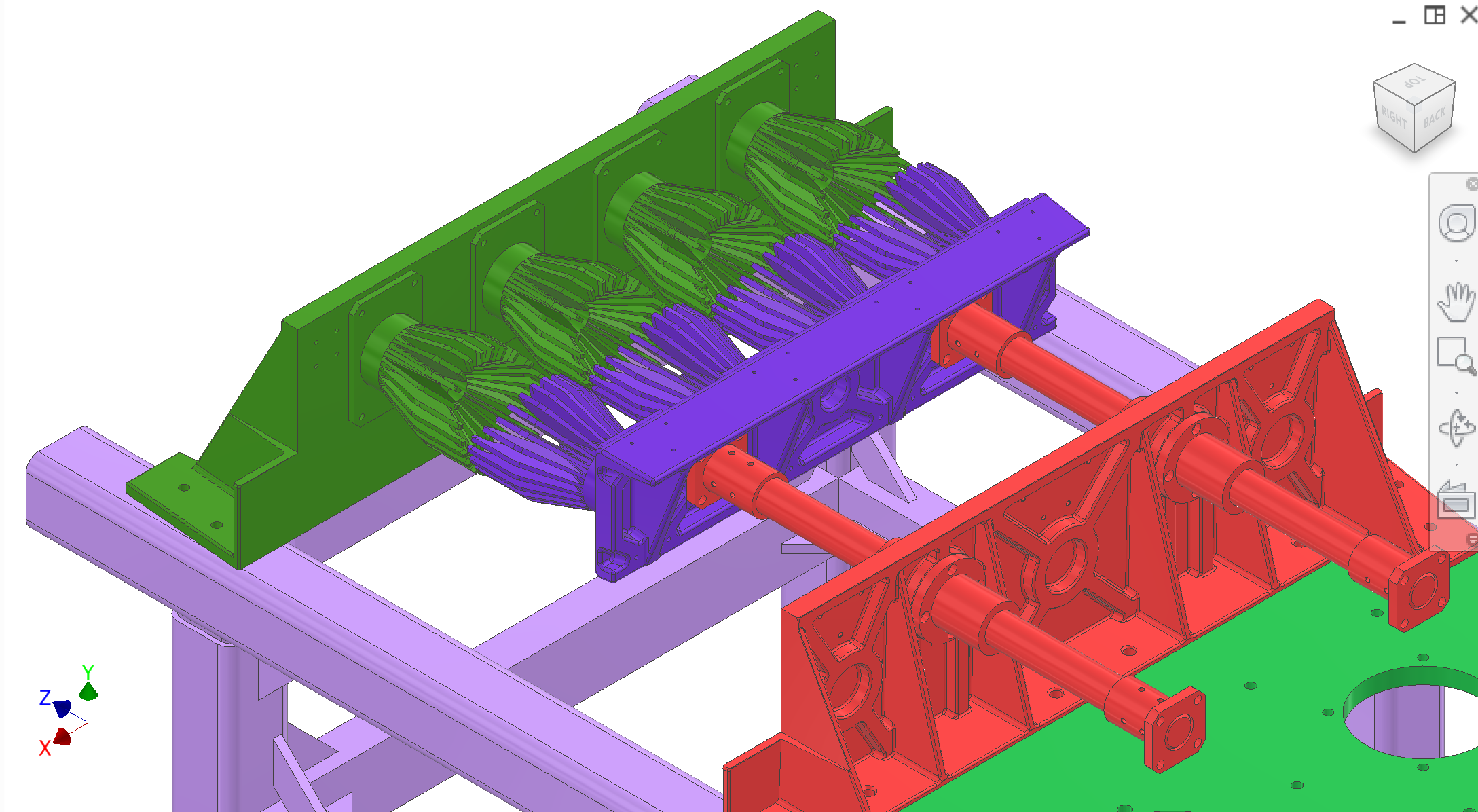
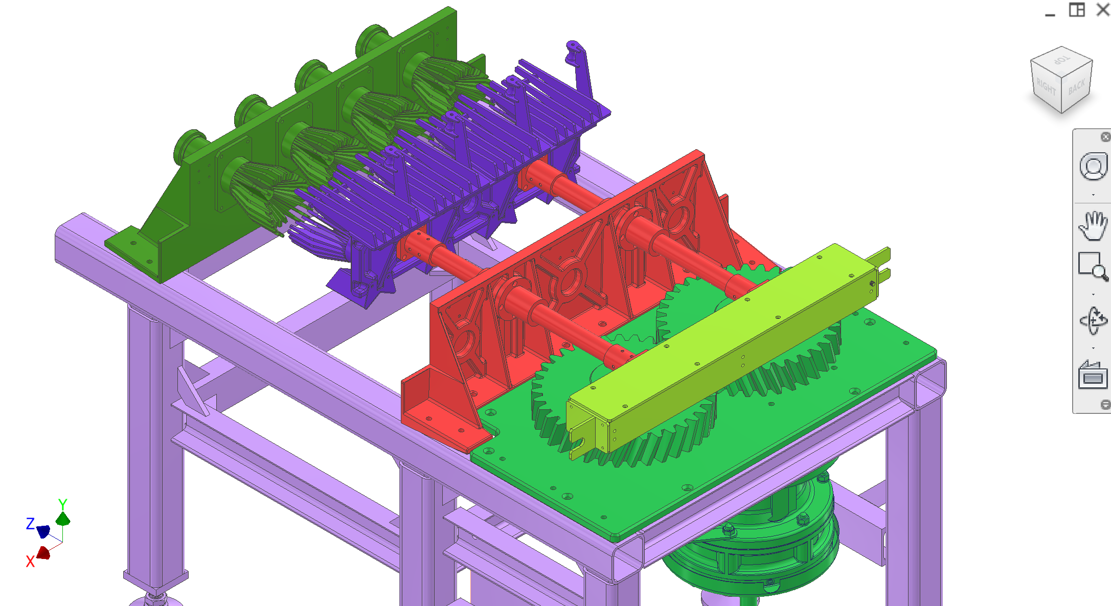
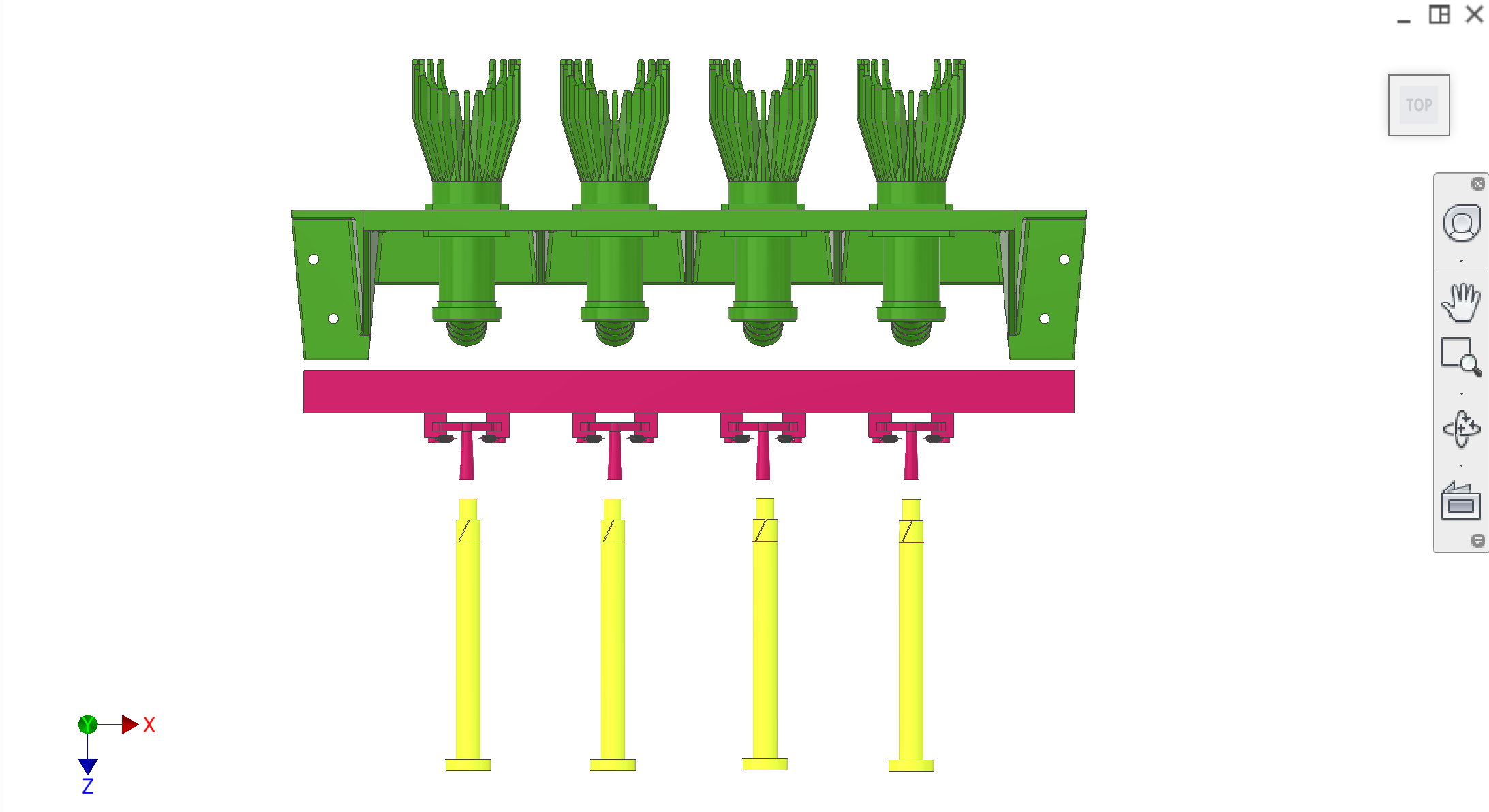
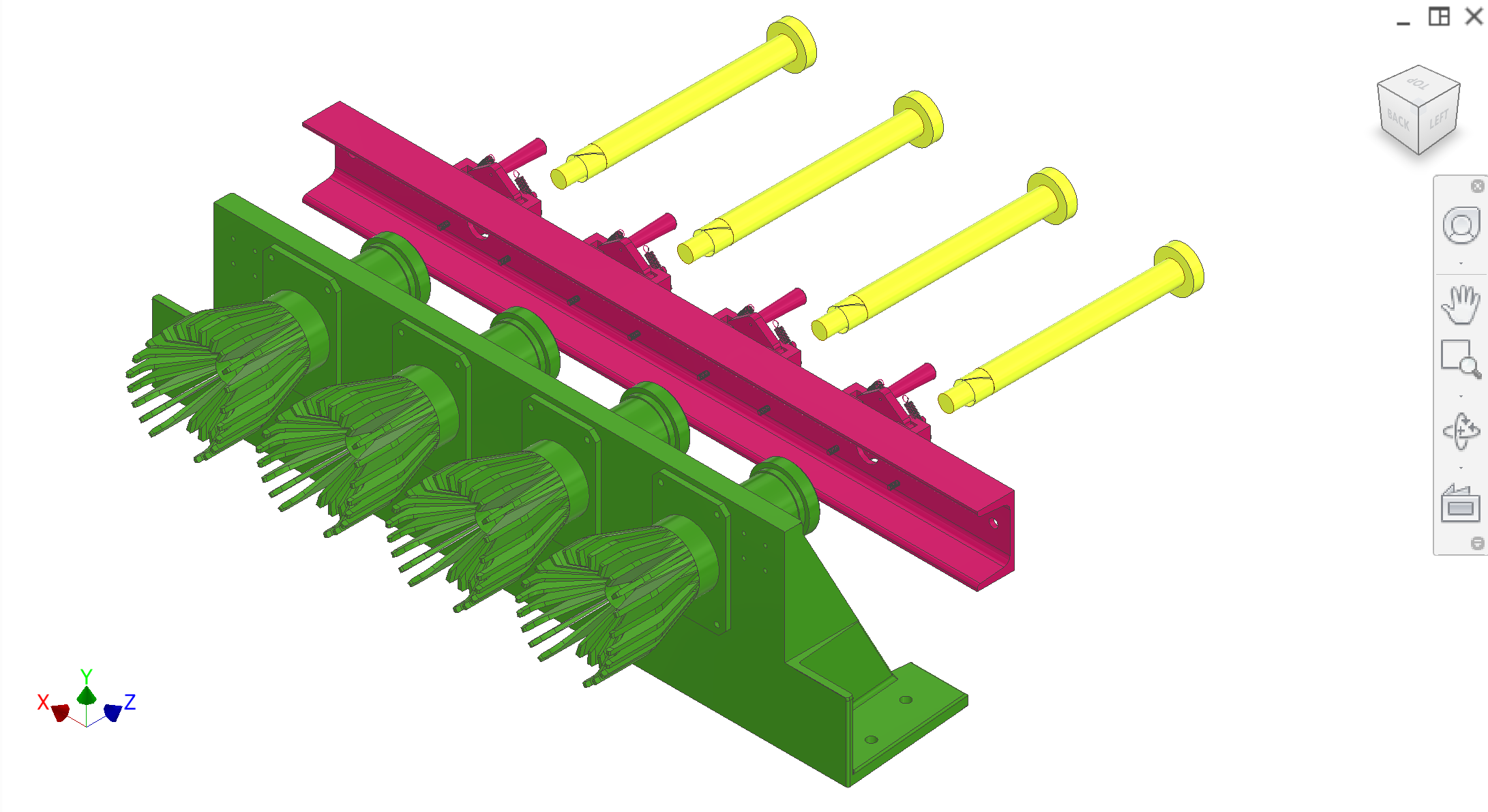
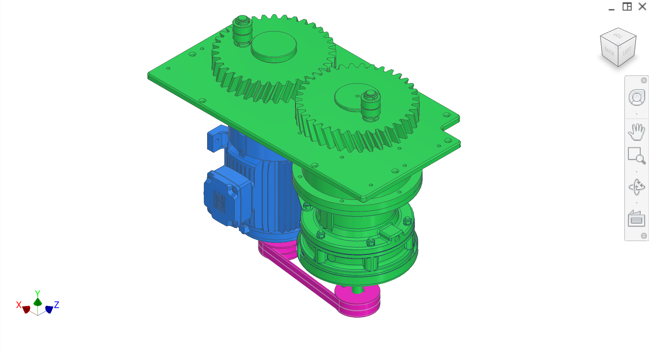
Close-ups of interfaces between core subsystems. Figures C1–C8 (C8 is an alternate drivetrain-enclosure view).
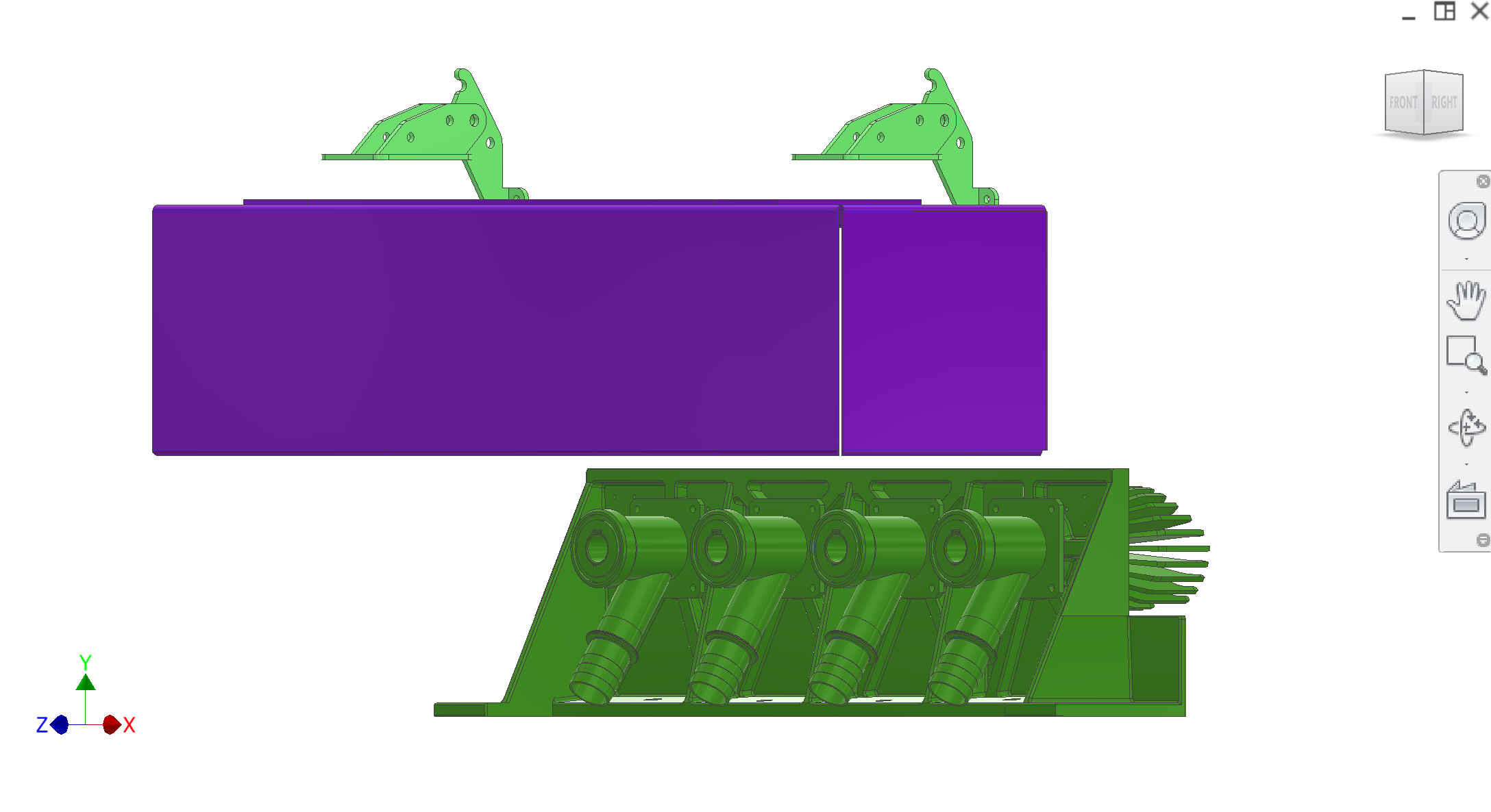
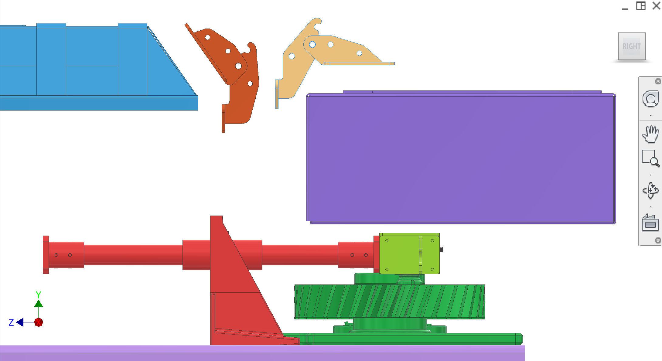
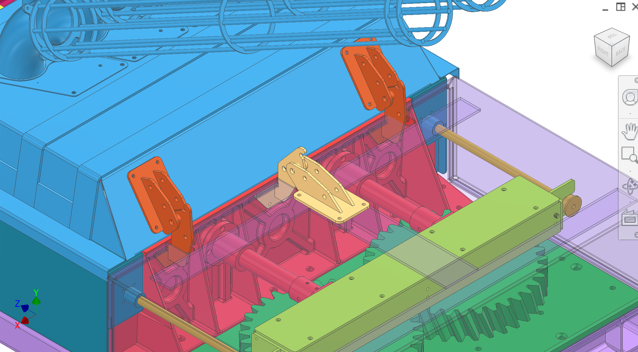
Figure C1. Core ejection / collection interface.
1 / 8
Discussion
Construction
Main frame: 80×80×5 GB/T square tubes as primary load members; #8 C-brackets for secondary/supporting members; gussets between members as shown in CAD; fully welded weldment. Leveling: McMaster 6111K669 M24 × 100 mm swivel leveling mounts on M24 tapped endplates at the six legs.
Mounting and dowels: Side rails and cross beams provide bolted interfaces (through-holes) for the three main plates. Plates are shimmed and aligned on those bolts first; dowel holes are created after alignment by drill + ream to H7 for repeatable rebuild—not by relying on pre-cut “dowel squares” in the rails as the primary locating scheme.
Detail and interfaces are owner-provided; final tolerancing and assembly are for contractors. See Questions for RFP to flush out parameters per subsystem and subassembly.
Rough design & intent
Status — Preliminary CAD exists (current height). Not released for fabrication; contractors are expected to propose DFM and tolerance/assembly improvements.
What the frame must do — Provide a stable, repeatable datum structure so drivetrain, transmission, extraction, and collection can be aligned and reassembled without loss of timing or bearing life.
Top interfaces — Three main mount plates (loaded/collection, transmission, drivetrain) mount from the top onto the frame side rails. Current concept includes dowels (H7) + shims; contractor may propose improved adjustment/locating strategy to manage weld distortion.
Known issues & risks
Weld distortion / flatness — Risk that the as-welded top interface surfaces are not flush/flat. Adjustable leveling feet exist, but plate-to-rail interface adjustability and/or shimming is expected to compensate for local distortion.
Alignment repeatability — Repeatable alignment after service is critical. The extraction module (driven peelers) must align concentrically with the collection-side peelers; misalignment risks collision and accelerated wear.
Under-machine clearance (3rd-party augers) — The machine is planned to sit on an elevated platform, so augers can be located underneath and the exact floor clearance is not a primary constraint. Still, for smaller pilot plants, extra clearance beneath the frame can be beneficial for auger installation/removal and service access; contractor to consider.
Collection area cover / user access — Current upward-opening plunger/collection lid blocks operator access close to the front. Alternate lid/hinge/cover approach may require changes to rail overhang and mounting features near the collection side.
DFM & manufacturing (China)
Weld + fixture plan — Provide recommended jigging and weld sequence to control distortion and achieve practical flatness/squareness at plate interfaces.
Post-weld machining vs adjustable interfaces — Recommend whether to machine pads/rails after welding, or instead use adjustable/shimmable plate interfaces to meet alignment requirements.
Member selection — Confirm local availability of 80×80×5 GB/T tube and GB/T #8 C-channel/C-brackets; propose equivalents if better for stiffness, distortion control, or fabrication simplicity.
Surface treatment — Frame is exposed to vapors/cleaning agents but is outside the main extraction chamber. Recommend a practical corrosion-resistant finish for this environment.
Optimizations sought
Repeatable assembly — A robust "align once, then dowel/ream" plan for mount plates and peeler datums.
Serviceability — Easy removal/reinstall of subsystems without re-shimming or re-alignment where possible.
Distortion tolerance — Reduce sensitivity to weld flatness via interface design and datums.
Operator access — Improve collection-area cover/lid concept so operators can stand close to the machine front.
Questions for contractor
Propose a weld sequence + fixture/jig approach to control distortion and hit practical flatness/squareness targets at the plate interfaces.
Recommend the datum scheme and locating strategy (dowels/H7, shims, adjustable mounts, machined pads) to ensure repeatable alignment after service removal.
Should we expect post-weld machining (and where), or can we avoid it with adjustable/shimmable interfaces? Provide trade-offs.
Recommend member/cross-bracing choices (GB/T #8 C-channel or alternatives) that are common in China and improve stiffness/distortion performance.
Propose a clearance strategy for third-party peel/core augers under the peel chute (envelope definition, adjustable height, removable/relocated lower cross-member, etc.).
Propose a collection-area cover/lid mounting concept that improves operator access while maintaining safety and stiffness.
Supply chain & alternates
Leveling mounts — Current spec: McMaster 6111K669 M24. Contractor to propose China-available equivalents if acceptable.
Profiles and plates — Prefer common GB/ISO profiles and stock sizes; propose equivalents where they reduce lead time or fabrication complexity.
Expected deliverables & acceptance
Deliverables — Updated weldment drawing pack (weld callouts), datum scheme, tolerance targets, recommended inspection checks, and an assembly/alignment/dowelization procedure for repeatable rebuilds.
Acceptance — Three mount plates can be aligned and remain aligned under operating loads; extraction-to-collection peeler alignment is repeatable after disassembly/reassembly; joints do not slip/fret under cyclic vibration/loads.
Design principles
These principles guide frame design and any changes to the current configuration.
Principle
Description
Stability
Resist deflection under operating loads so alignment and timing are maintained. Stiffness of the welded structure and plate interfaces is critical.
Alignment
The three main interfaces (drivetrain, transmission, loaded mount plates) shall be located and oriented so drive shafts, bearings, and peelers align to design intent. Dowels and H7 holes provide repeatable alignment after disassembly.
Force transmission
Reaction forces from drivetrain and plunger shall be carried through the frame into the floor without local distortion. Load paths clear; joints adequate.
Repeatability
Plates and brackets removable and remountable without loss of alignment. H7 holes and dowels define the datum; shims for fit-up.
Serviceability
Subassemblies removable and reinstallable for maintenance. No permanent "fit once" alignment.
Manufacturability
Materials, weldability, and assembly sequence achievable by the fabrication partner (e.g. Sean/YES).